Category: Cisco

  • UCS B-Series Start to Finish: Part 2

    UCS B-Series Start to Finish: Part 2

    After the initial setup is done, I recommend to go ahead and install the latest available firmware  to get the most out of your environment. First, go to http://www.cisco.com, and from the Support Menu, click “All downloads.”

    Image 1. Cisco Support Site – > All Downloads

    Screenshot 2016-05-05 14.30.02

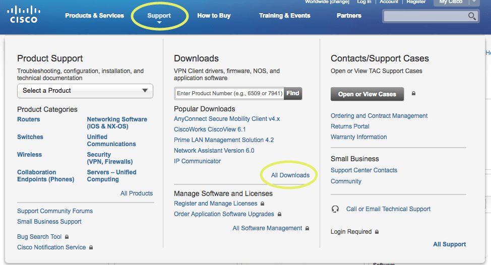
    Note: just hover over Support, don’t click

    Image 2. Select The UCS B-Series Blade Server Software

    Screenshot 2016-05-05 14.31.58

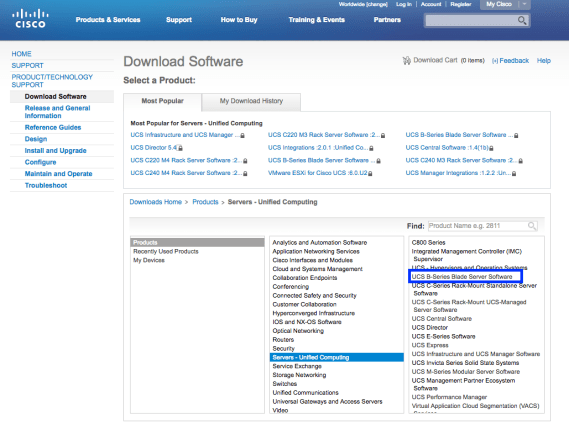
    Image 3. Select the Server Software Bundle

    Screenshot 2016-05-05 14.33.05

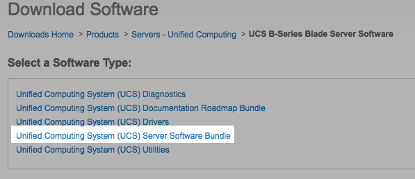
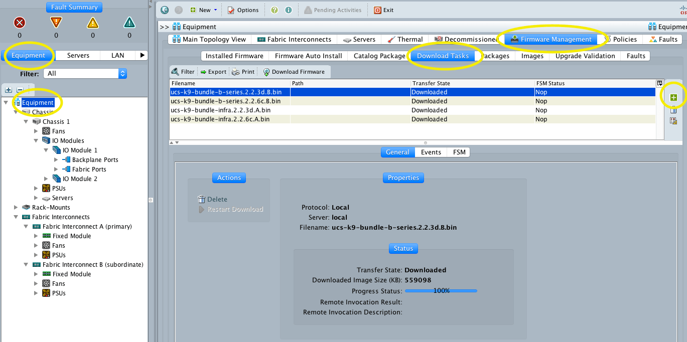
    Image 4. Select the UCS Manager version and download the respective bundles.

    Screenshot 2016-05-05 14.37.42

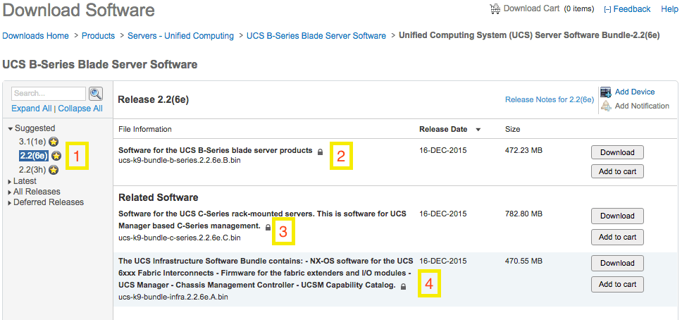
    Number one (1) is the UCS Manager release version, number two (2) is the Blade Firmware, number three (3) is the bundle for the C-series. The C-Series bundle is not necessary, but it’s recommended to upload it too. Number four (4) is the UCS Manager and the FI firmware. With this, now your are ready to start the software update.

    Phase 1: Pre-Work

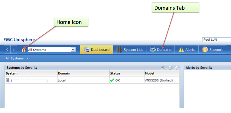
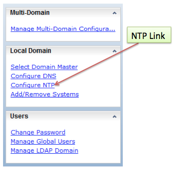
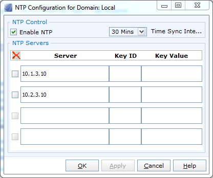
    • Check that the NTP is configured and working (view Figure 6 on Part 1)
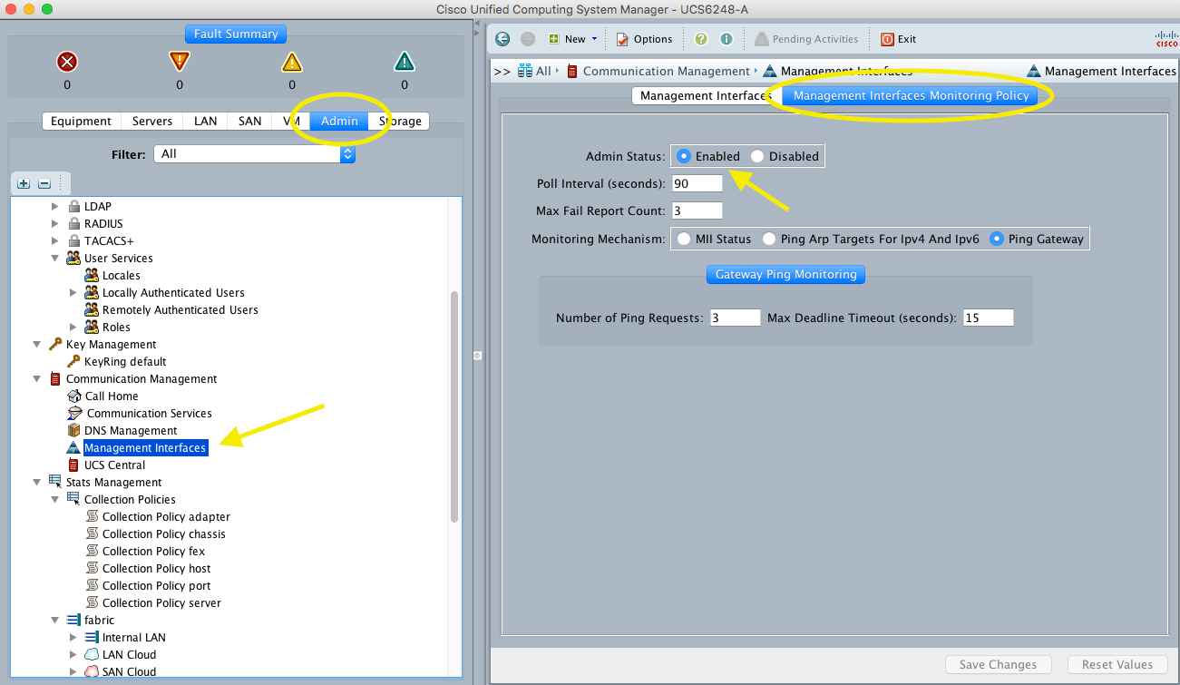
    • Take note of the management interfaces IP addresses and check that the admin status is enabled.

    Screenshot 2016-05-05 14.56.21

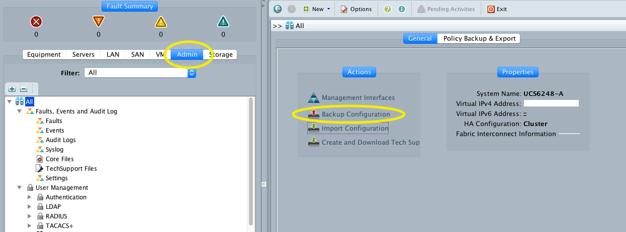
    • Backup the UCS configuration

    Screenshot 2016-05-05 15.02.40

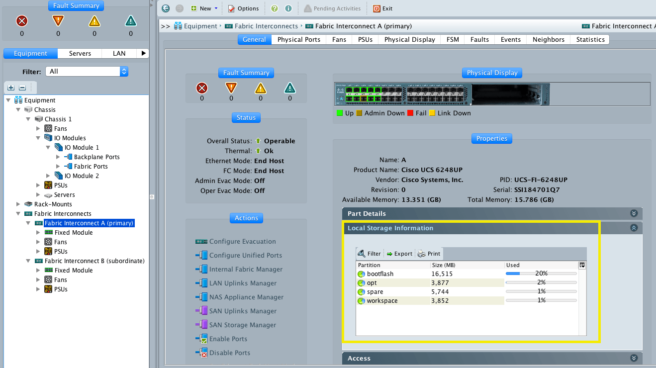
    • Verify the status of each FI, the status should be ok and green before proceeding.

    Screenshot 2016-05-05 15.07.47

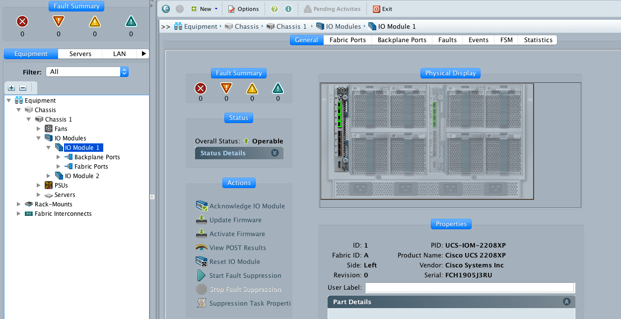
    • Verify that the IO modules are up and operable

    Screenshot 2016-05-05 15.12.06

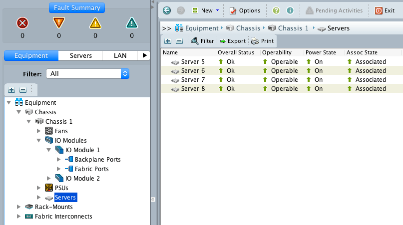
    • If the environment has been previously configured and is in production, check that all the servers (and all the rest of the equipment in general) are working correctly.

    Screenshot 2016-05-05 15.14.29

    • Verify that there is available capacity for the upgrade. If space is low delete any packages that are not in use (from the same place we will upload the packages later).

    Screenshot 2016-05-05 15.22.27

    • Before upgrading to Cisco UCS Manager Release 3.1, ensure that the key ring in use has a modulus size of 2048 bits or more by doing the following:
      • Connect to the UCS manager via ssh
      • Verify the modulus size of the key ring in use by using the following commands:
    UCS-A# scope security
    UCS-A /security # scope keyring keyring-name 
    UCS-A /security/keyring # show detail
    • If the default key ring is in use and has a modulus size less than 2048 bits, reconfigure the modulus size to 2048 bit or more, and regenerate the certificate by using the following commands:
    UCS-A# scope security
    UCS-A /security # scope keyring default
    UCS-A /security/keyring # set modulus mod2048
    UCS-A /security/keyring # set regenerate yes
    UCS-A /security/keyring # commit-buffer
    UCS-A /security/keyring # show detail
    • Upload the packages, click on the plus sign to upload the files.

    Screenshot 2016-05-05 15.26.44.png

    Check the Cisco UCS Manager Firmware Management Guide, Release 3.1

    • If the UCS Manager cluster uses the Fiber Interconnect 6296, please verify the Hardware version. SSH into the cluster and issue the “connect nxos” command, then “show module”

    Screenshot 2017-07-06 11.41.23

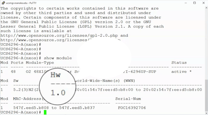
    • If the system has version 1.0 installed, then open a support case with Cisco to update it to version 1.1.

    Phase 2: UCS Manager

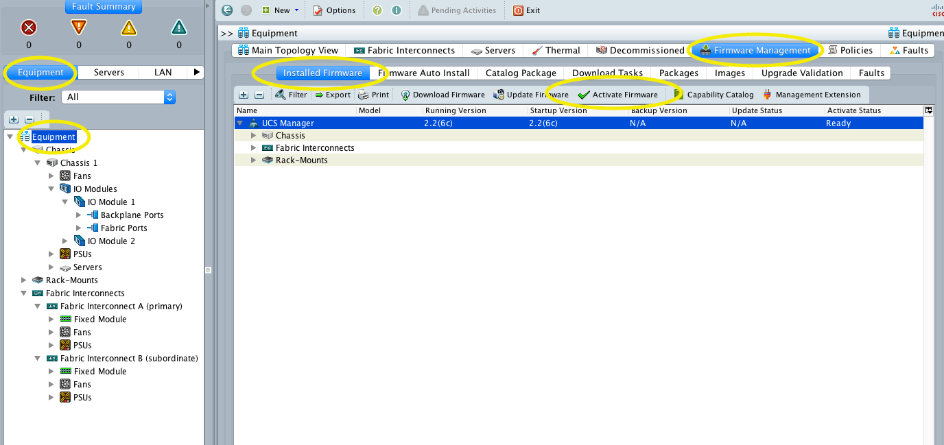
    First, we update the UCS Manager software.

    • Equipment->Equipment->Firmware Management->Installed Firmware->Activate Firmware

    Screenshot 2016-05-05 15.52.25

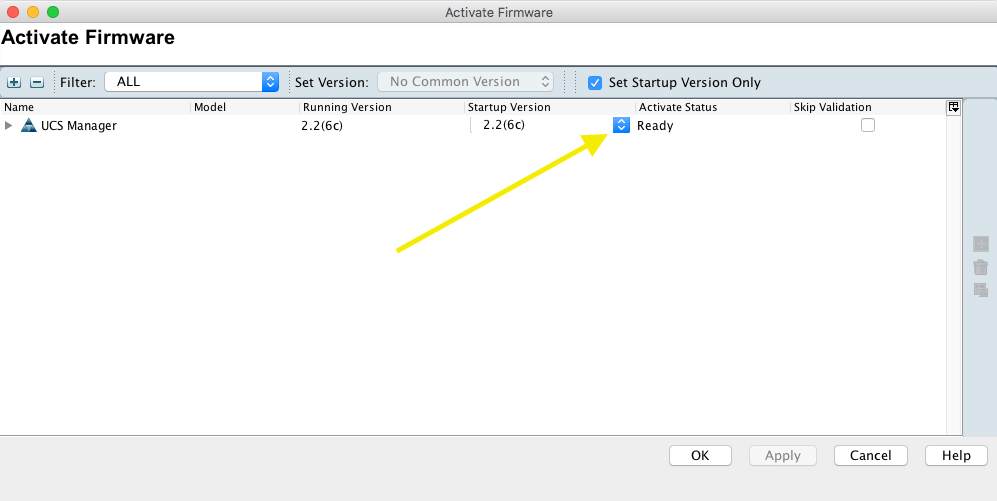
    • Click on the drop-down menu to select the new version

    Screenshot 2016-05-05 15.52.15

    • In case this error message pops:

    Screenshot 2017-07-06 11.50.56.png

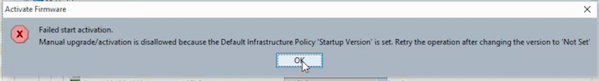
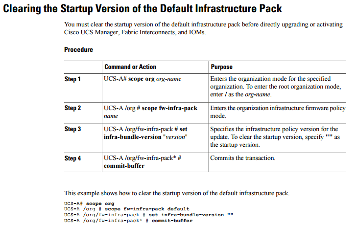
    • Go ahead and clear the start up version and try again:

    cli-startup-version

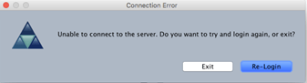
    • Re-login after a few minutes

    relogin

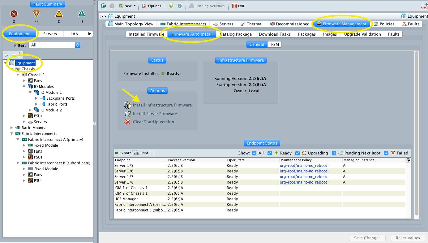
    Phase 3: FI Firmware

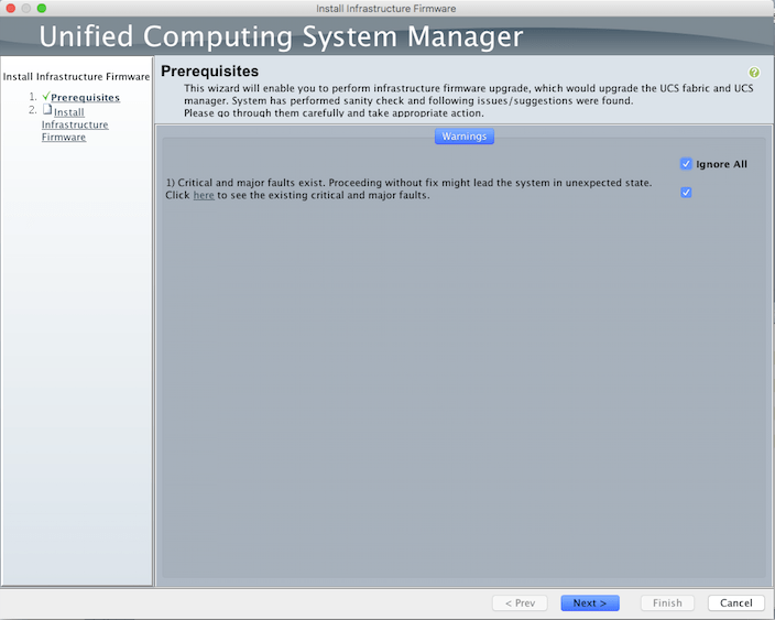
    • Equipment->Equipment->Firmware Management->Firmware Auto Install and then Click Install Infrastructure Firmware

    Screenshot 2016-05-05 16.04.55

    • Select Ignore All and click Next.

    Screenshot 2016-05-05 16.34.25.png

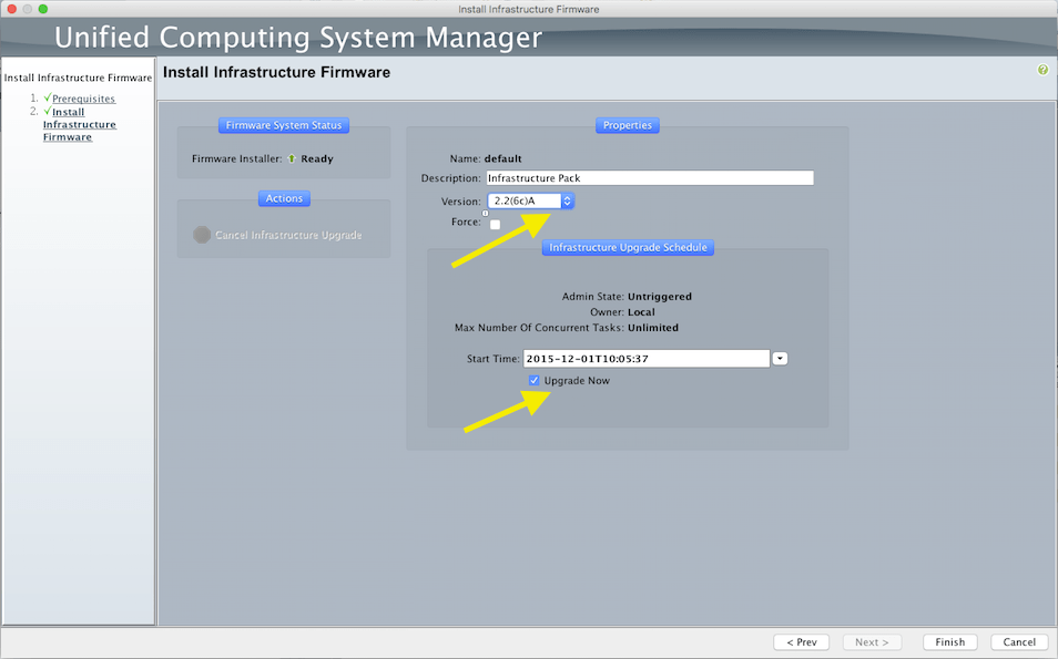
    • Select the version from the drop-down menu, check the Upgrade Now button and Click Finish.
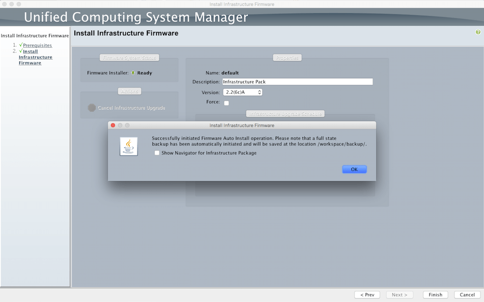
    Screenshot 2016-05-05 16.35.46.png

    • Click OK

    Screenshot 2016-05-05 16.41.49.png

    • Verify the pending activities on top of the UCS manager to acknowledge the reboot of the FI’s. Verify that the hosts are working properly before the acknowledge.
    • Click Yes
    • Click OK
    • Monitor the Progress, this could take 40 minutes per FI

    Screenshot 2016-05-05 16.42.08.png

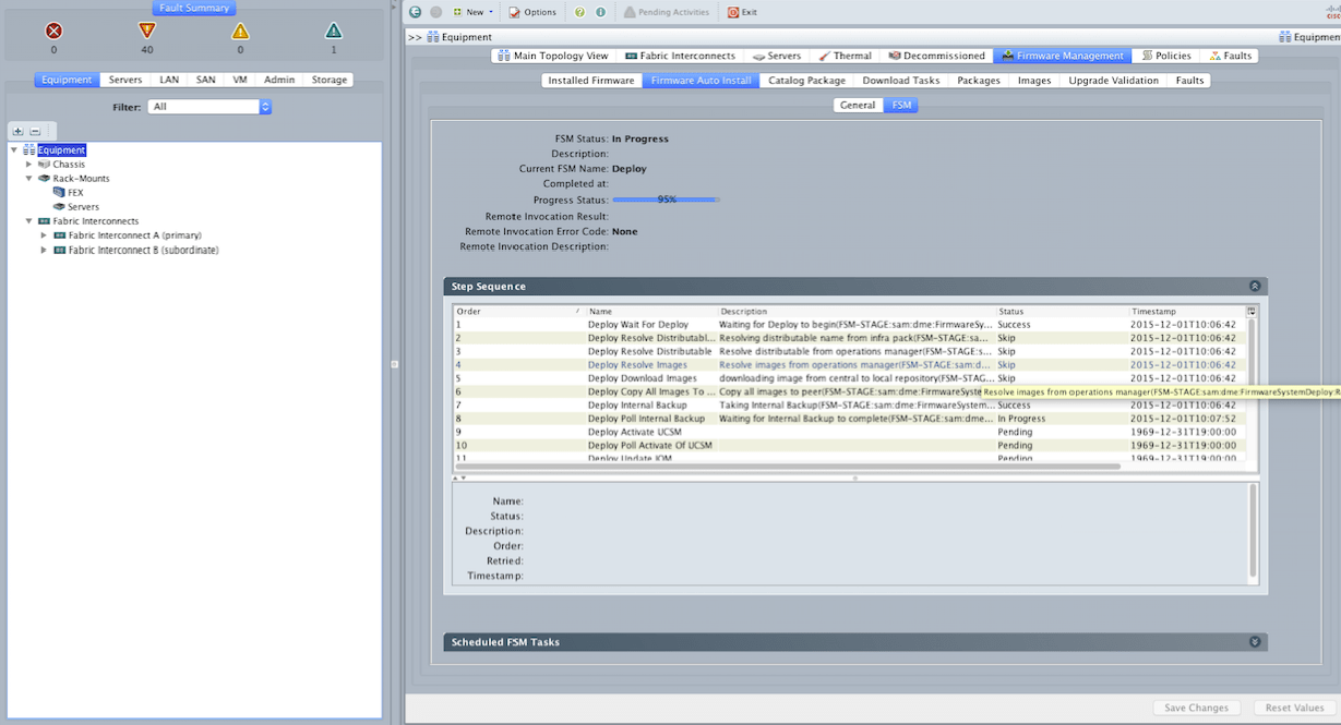
    • When the primary FI reboots, the UCS manager will disconnect, and you will have to re-login. Check the progress and reboot the secondary FI when the option appears in pending activities on top.

    Phase 4: Blade Servers

    Now is the blade server turn. If the system is in production, check that all Service Profiles have the Maintenance Policy set to User Ack to avoid an immediate reboot of the servers. Before continuing, it is advisable to check that all components are up and operable.

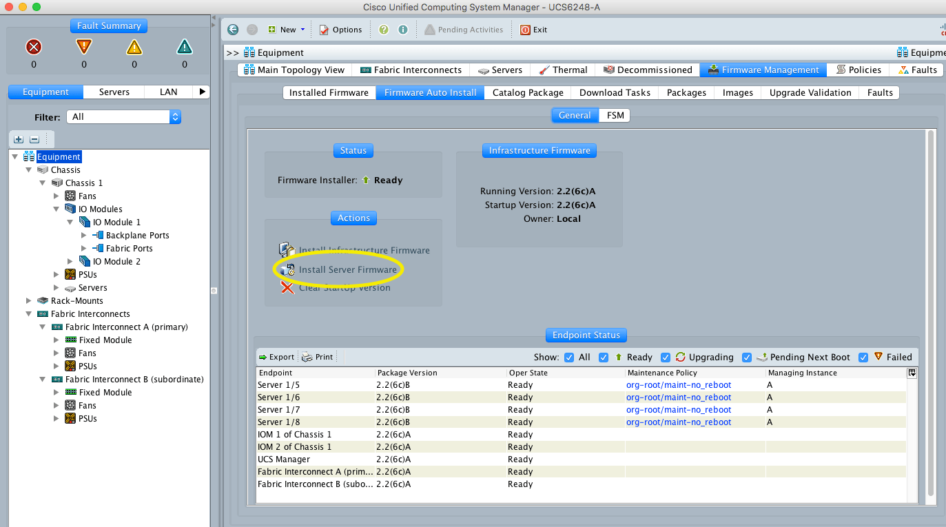
    • Click on the Install Server Firmware link

    Screenshot 2016-05-05 16.53.33.png

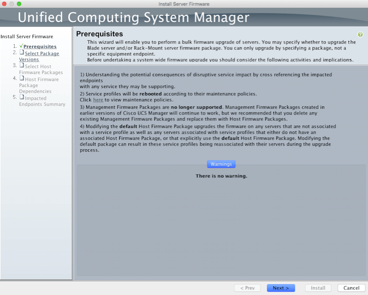
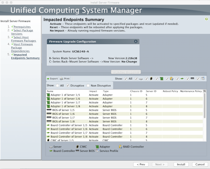
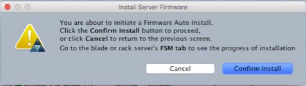
    • Follow the wizard clicking next, at the end click Install and click Confirm Install to the pop-up windows.

    Screenshot 2016-05-05 16.55.32.png

    Screenshot 2016-05-05 16.57.23.png

    Screenshot 2016-05-05 16.57.54.png

    • Monitor the progress and check the Pending Activities on the top for the Acknowledge, if the system is in production make sure you schedule a maintenance window for this.

    Screenshot 2016-05-05 16.59.21.png

    An alternative would be to create a new Firmware Policy with the new version and then apply the policy to the Service Profile or the Service Profile Template.

    With the system at the latest software version, we are ready to continue with the configuration of the Pools, Policies, and Templates.

    Part III: Pools and Policies

    Part IV: Service Profile Templates

    Part V: Storage


  • UCS B-Series Start to Finish – Part 1

    UCS B-Series Start to Finish – Part 1

    I always wanted to write about the UCS B-Series installation process, but I was always in a hurry and could not take snapshots of a real installation. Here is a summary of that I did on my last installation:

    Part I: Initial Setup

    First, you need to rack and cable the equipment. For the correct way to install the equipment in the rack please check the Cisco UCS 5108 Server Chassis Installation Guide. In this guide, you can use pages 41-49 for the Chassis rack instructions and page 81 for the power cables needed. Then check the Cisco UCS 6200 Series Fabric Interconnect Hardware Installation Guide on pages 26 to 28. The next step would be to connect to the console port in the Fiber Interconnect (FI).

    FI-Cross-Connect-Ports

    From the Guide (pp. 55-56):

    1. Plug the RJ-45 end of the serial management cable into the Console port on the fabric interconnect, and connect the DB-9 male end into the serial port on a laptop or other computer. If the computer you will use does not have a serial port, you will need to use the Serial to USB adapter. Be sure to install the drivers for your adapter.
    2. Start your terminal software.
    3. Configure the terminal software as follows:
      • The COM port for the connection you are about to establish is the connection to the fabric interconnect. You may need to look in the computer’s device manager to confirm this. Example COM1 or COM5.
      • The other connection parameters are 9600 baud, 8 data bits, no parity, 1 stop bit.
    4. Use the terminal software’s command to open the connection to the Fabric Interconnects. A session window will start, let’s take a look at the next to screenshots:

    Figure 2. Fiber Interconnect Cluster Initial Configuration (FI-A)

    UCS-FI-Setup-1

    Figure 3. Fiber Interconnect Cluster Initial Configuration (FI-B)

    UCS-FI-Setup-2

    Now you are ready to connect to your UCS manager using your browser (Using the Cluster IPv4 address from the first screenshot).

    Configure the Fiber Interconnect ports used to connect the Chassis as Server Ports. This will acknowledge the chassis and let you configure the rest.

    Figure 4. Set the Chassis ports to Server Ports

    Screenshot 2016-05-05 17.03.35

    I would like to show a few basic initial steps before we are ready to upgrade the firmware. After login into the UCS manager using your browser, change the Power Policy to “grid”. Equipment->Policies->Global Policies->Grid

    Figure 4. Power PolicyScreenshot 2016-05-05 14.03.18

    The grid redundant configuration is sometimes used when you have two power sources to power a chassis or you require greater than N+1 redundancy. If one source fails (which causes a loss of power to one or two power supplies), the surviving power supplies on the other power circuit continue to provide power to the chassis. A common reason for using grid redundancy is if the rack power distribution is such that power is provided by two PDUs and you want the grid redundancy protection in the case of a PDU failure.

    Another set of basic configuration parameters: the Call Home, the NTP and the Timezone.

    Figure 5. Call Home Setting (leave it off until everything has been configured)

    Screenshot 2016-05-05 14.02.14

    Figure 6. NTP and Timezone Settings

    Screenshot 2016-05-05 14.08.15

    In the next new blogs, I will discuss the rest of the steps for configuration.

    Part II: Firmware Upgrade

    Part III: Pools and Policies

    Part IV: Service Profile Templates

    Part V: Storage

  • Brocade Command Line

    I love the Brocade GUI, but I hate Java. I usually find my way with the workarounds out there to be able to display the Java plugins, but this time I wasted too much time on something that can be done in the command line. I was at a customer’s site and we added a few servers to the Fabric. These are the commands I used to update the zoning.

    1. switchshow: Displays switch and port status.
    2. portloginshow <port #>: display WWPN on NPIV ports
    3. alishow: Displays zone alias information.
    4. cfgshow: Use this command to display zone configuration information.
    5. zoneshow: Displays zone information
    6. zonehelp: To help find the commands you will need.

    With the information I gathered from the commands above I was able to add aliases, zones and then add the zone to the current configuration. The save and enable the config.

    Fabric B:

    alicreate “dc3_esx_11”, “50:01:43:80:24:d2:9b:b6”
    alicreate “dc3_esx_12”, “50:01:43:80:24:d2:9e:ee”
    alicreate “dc3_esx_13”, “50:01:43:80:24:d2:7d:de”

    zonecreate “dc3_sp_01_dc3_esx_11”, “dc3_sp_01;dc3_esx_11”
    zonecreate “dc3_sp_02_dc3_esx_11”, “dc3_sp_02;dc3_esx_11”
    zonecreate “dc3_sp_01_dc3_esx_12”, “dc3_sp_01;dc3_esx_12”
    zonecreate “dc3_sp_02_dc3_esx_12”, “dc3_sp_02;dc3_esx_12”
    zonecreate “dc3_sp_01_dc3_esx_13”, “dc3_sp_01;dc3_esx_13”
    zonecreate “dc3_sp_02_dc3_esx_13”, “dc3_sp_02;dc3_esx_13”

    cfgadd “Running_Config”, “dc3_sp_01_dc3_esx_11;dc3_sp_02_dc3_esx_11”
    cfgadd “Running_Config”, “dc3_sp_01_dc3_esx_12;dc3_sp_02_dc3_esx_12”
    cfgadd “Running_Config”, “dc3_sp_01_dc3_esx_13;dc3_sp_02_dc3_esx_13”

    cfgSave
    cfgEnable “Running_Config”

    Fabric A:
    alicreate “dc3_esx_11”, “50:01:43:80:24:d2:9b:b4”
    alicreate “dc3_esx_12”, “50:01:43:80:24:d2:9e:ec”
    alicreate “dc3_esx_13”, “50:01:43:80:24:d2:7d:dc”

    zonecreate “dc3_sp_01_dc3_esx_11”, “dc3_sp_01;dc3_esx_11”
    zonecreate “dc3_sp_02_dc3_esx_11”, “dc3_sp_02;dc3_esx_11”
    zonecreate “dc3_sp_01_dc3_esx_12”, “dc3_sp_01;dc3_esx_12”
    zonecreate “dc3_sp_02_dc3_esx_12”, “dc3_sp_02;dc3_esx_12”
    zonecreate “dc3_sp_01_dc3_esx_13”, “dc3_sp_01;dc3_esx_13”
    zonecreate “dc3_sp_02_dc3_esx_13”, “dc3_sp_02;dc3_esx_13”

    cfgadd “Running_Config”, “dc3_sp_01_dc3_esx_11;dc3_sp_02_dc3_esx_11”
    cfgadd “Running_Config”, “dc3_sp_01_dc3_esx_12;dc3_sp_02_dc3_esx_12”
    cfgadd “Running_Config”, “dc3_sp_01_dc3_esx_13;dc3_sp_02_dc3_esx_13”

    cfgSave
    cfgEnable “Running_Config”

    And there you have it, three servers with two HBA’s each, added to a VNX with two FC connections to each Fabric. In this case the original configuration doesn’t make any distinctions between servers on each switch. I always try to add HBA1 or HBA2, or SPA_P0 and SP_P1, but the approach used here makes it very simple. Check the complete guide:

    http://www1.brocade.com/downloads/documents/product_manuals/B_SAN/FOS_CmdRef_v700.pdf

  • NX-OS Basic Commands Cheat Sheet

    I am going to start today some hands on labs to practice for my CCNA (DCICN) Data Center test (640-911). This post is going to look more like a series of questions and answers with the commands used in the exercises.

    1.  To delete the start-up configuration

    Switch#write erase boot
    Switch#reload

    2. To enter Global Configuration Mode

    Switch#config
    Switch(config)#

    3. How to the save the Configuration

    Switch#copy running-config start-config or
    Switch#copy run star

    4. Set the hostname

    Switch#config t
    Switch(config)#hostname switchA

    5. Setting up the management ip address and description

    switchA#config t
    switchA(config)#int mgmt0
    switchA(config-if)#ip address 10.10.10.2 255.255.255.0
    switchA(config-if)#description management address
    switchA(config-if)#end
    switchA#

    6. Creating VLANs

    switchA#
    switchA(config)#vlan 10
    switchA(config-vlan)#name meaningful-name
    switchA(config-vlan)#exit
    switchA(config)#

    7. Assign an interface to a vlan

    switchA#config t
    switchA(config)#int e3/1
    switchA(config-if)#switchport
    switchA(config-if)#switchport mode access
    switchA(config-if)#switchport access vlan 10
    switchA(config-if)#end
    switchA(config)#

    8. RIP

    Nexus7k(config)# feature rip
    Nexus7k(config)# router rip RodzRIP
    Nexus7k(config-router)# address-family ?
    ipv4 Configure IPv4 address-family
    ipv6 Configure IPv6 address-family
    Nexus7k(config-router)# address-family ipv4 unicast
    Nexus7k(config-router-af)# int e3/1 - 2
    Nexus7k(config-if-range)# ip router rip RodzRIP

    9. EIGRP

    Nexus7k(config)# feature eigrp
     Nexus7k(config)# router eigrp RodzEIGRP
     Nexus7k(config-router)# au?
     authentication autonomous-system
     Nexus7k(config-router)# autonomous-system ?
     <1-65535> Local AS number
     Nexus7k(config-router)# autonomous-system 100
     Nexus7k(config-router)# int e3/1 - 2
     Nexus7k(config-if-range)# ip router eigrp RodzEIGRP

    10. OSPF

    Nexus7k(config-if-range)# feature ospf
    Nexus7k(config)# router ospf  JRVOSPF
    Nexus7k(config-router)# int e3/1 -2
    Nexus7k(config-if-range)# ip router ospf JRVOSPF area 0

    11. Configure ports for routing, Example ports e3/1 and e3/2

    Nexus7(config-if)# int e3/1
    Nexus7(config-if)# no switchport
    Nexus7(config-if)# ip address 172.16.10.1/24
    Nexus7(config-if)# no shutdown
    Nexus7(config-if)# int e3/2
    Nexus7(config-if)# no switchport 
    Nexus7(config-if)# ip address 172.16.20.1/24
    Nexus7(config-if)# no shutdown

    12. Configure a static route to remote network 192.168.10.0/24

    Switch#conf t
    Switch#(config)#ip route 192.168.10.0/24 e3/1 172.16.10.2

    13. VLAN TRUNK

    Switch#conf t
    Switch#(config)#int e3/28
    Switch#(config-if)#switchport
    Switch#(config-if)#switchport mode trunk
    Switch#(config-if)#switchport trunk allowed vlan add 10
    Switch#(config-if)#switchport trunk allowed vlan remove 10
    Switch#(config-if)#end

    14. Changing Native VLAN

    Switch#conf t
    Switch#(config)#int e3/28
    Switch#(config-if)#switchport
    Switch#(config-if)#switchport mode trunk
    Switch#(config-if)#switchport trunk native vlan 660

    15. Configuring VTP

    Switch#conf t
    Switch#(config)#feature vtp
    Switch#(config)#vtp mode server
    Switch#(config)#vtp domain <domain-name>
    Switch#(config)#vtp password <password>
    Switch#(config)#vtp version 2
    Switch#(config)#vtp pruning
    Switch#(config)#sh vtp status

    16. Configuring Inter-VLAN Routing

    feature interface-vlan
    interface vlan 10
    ip address 172.16.10.1/24
    int vlan 20
    ip address 172.16.20.1/24
    int vlan 30
    ip address 172.16.30.1

    17. STP

    show spanning-tree
    conf t
    spanning-tree vlan 1 priority 4096 (multiples of 4096 up to 61440)
    int e3/40-44
    spanning-tree port type edge (for hosts)
    int e3/45-48
    spanning-tree port type network (for inter switch links)

    18. Set a switch as root bridge

    spanning-tree vlan 1 root primary

    19 port-channels

    interface port-channel 1
    int e3/31-38
    switchport
    switchport mode  trunk
    channel group 1 mode on
    channel group 1 force mode on

    20. Show the forward/filter table

    show mac address-table

    21. Show the STP root bridge for a VLAN

    sh spanning-tree
    sh spanning tree vlan <vlan#>

    22. Configure a switch port to not transition through STP

    spanning-tree port type edge

    23. Show port channel

    sh interface port-channel number

    24 ACL To deny access to host 172.16.50.5 for telnet and ftp:

    access-list 110 deny tcp any host 172.16.50.5 eq 21
    access-list 110 deny tcp any host 172.16.50.5 eq 23
    access-list 110 permit ip any any
    int e3/1
    ip access-group 110 out

    25. Named ACL

    ip access-list Deny_FTP
    deny tcp any host 10.10.10.10 eq ftp
    permit ip any any
    int e3/2
    ip accès-group Deny_FTP out
    sh access-lists

    26. Configure Session

    config session <session name>
    ....
    verify
    commit

    27. Object Groups

    object-group ip address <name>
    10.0.0.0/8
    172.16.0.0/12
    192.168.0.0/24
    show object group <name>
    10 10.0.0.0/8
    20 172.16.0.0/12
    30 192.168.0.0/24
    Nexus7(config)# object-group ip port Permit_Ports
    Nexus7(config-port-ogroup)# range 2011 2099
    Nexus7(config-port-ogroup)# eq 31156
    Nexus7(config-port-ogroup)# gt 32655
    Nexus7(config-port-ogroup)# show object-group Permit_Ports
    Protocol port object-group Permit_Ports
            10 range 2011 - 2099
  • Super Tech Resource

    Suddenly you realize it, you are an expert at so many irrelevant things. This happened to you?, if you’ve been on IT for a while and you are still actually doing instead of managing, then you may end up rotting with some technology that is dying. When someone claims is a Cloud XXX, what do you expect from them? Well I found these skills for a Cloud Engineer job from a really cool company:

    • A mastery of Linux. This means: you know why things work on a Linux system, not just how to configure them
    • Experience developing enterprise application architectures to meet business requirements in complex environments
    • Knowledge and experience with large-scale systems integration involving private, hybrid, and public cloud platforms
    • Understanding of cloud orchestration frameworks, enterprise IT service provisioning tools, and their role in IT transformation
    • Experience with public and private cloud, including OpenStack and AWS
    • Experience with configuring: OpenStack Ceilometer, Cinder, Glance, Heat, Keystone, Nova, Neutron, Swift
    • Experience with virtualization, including: KVM, Xen, and VMWare
    • Experience with RabbitMQ / AMQP, Puppet, LDAP, NFS, and RHCS
    • Experience administering CentOS or Ubuntu
    • Able to write software in Python or some other administrative language
    • Able to read and perform debugging of C / C++ / Java programs.  Being able to write programs in these languages is even better!
    • Experience supporting or maintaining MySQL, MongoDB, and Couchbase

    How do I get these? I mean all of them. Is it really something achievable? For example, take virtualization. How much time does it take to be a VMware master? Then learn enough KVM and Xen to be able to master all three. I know it depends on how smart you are, but also on how much hands experience you can get. What if you are an expert in Solaris or AIX, but not Linux. I wonder if such a person exists. I would like to work with this person and learn everything I could. In the meantime maybe I should apply for an internship with this company to be able to master every skill in this list, and then hope they are not replaced by new technology and become irrelevant again.

    As always pardon my English, I just feel that if I write these in Spanish nobody would ever read them (not that anyone read them anyway :P)

  • Just don’t follow your dream

    Ok, I have your attention, now let me explain myself. I come from a home in which my father always worked Monday to Saturday, he doesn’t know what the word vacation means, and he is still working at age 74. He never bought anything that was not essential to us. Good house (of course no mortgage), food and good education. I once asked my parents if they could buy an ATV for me if I obtained good grades, and they said that the good grades were for me not for them (kind of saying there is no way you are going to blackmail us with that), but really just saying that it was in my best interest to do well in school.

    Enough about family history, here is what I mean. You really have to setup a goal, but then stop thinking about the end result and start thinking on how to get there. Dedicate all your resources to those little things that will allow you to reach that goal. Stop daydreaming, be practical and don’t waste your time on things that will not contribute to your mission.

    If you want to be the best basketball player, then research what you have to do and then do it six days a week for the amount of time needed to create results, don’t waste you time playing a video game or fantasizing about wining the slam dunk contest.

    Those of us in the IT business will be challenged multiple times during our career. This is something you learn and relearn, apply the useful stuff and hopefully discard what doesn’t work. Keep your goals clear and well defined, but never hold back, shoot for the moon.


  • Cloud Something

    Cloud Something

    The World Cup started, so I will cheer for the one who seems to be wining at any give point. Yes I know it sounds not very loyal from my part, but a man does what a man needs to do, right? Anyway I’ve been out for a while (again) but I want to share my thoughts on the cloud, but the cloud that its beginning to be seen in the TV and movies, yesterday I saw a movie trailer and the actors were saying something about “nobody understands the cloud”. Well that may be the case, I mean probably big companies do, but believe me that some people out there are still trying to understand virtualization so you can imagine.

    The issue is more on whether you continue on the race to the bottom, or do you jump on this big opportunity. I believe that is possible to consolidate beyond what we’ve achieved with virtualization. We are talking about Virtual Data Centers, having a couple of physical locations, but seen as one.

    Who are the players? Well, this looks like the gold rush., everyone have some sort of initiative. So please take a look at you situation. Do you work in an environment (I guess mostly tech) that will be affected by this cloud storm? Make your move now, don’t get caught without an emergency plan.

    Remember when you see clouds, there may be a storm coming.

  • EMCWORLD 2014

    Finally I made it to Las Vegas. It is fantastic!, I’m starting the third day and I’ve enjoyed every single minute of it. Honestly, although I liked all the sessions, Bear Grylls talk on extra-ordinary was my favorite. When you absolutely think there is nothing left on you to give, that is the moment you know you have to give a little bit more., that is the “Q”. We can’t wait to get back home to pass the message, the third platform is here, we as IT professionals need to prepare for the software defined everything. This is just the logical next step, the software have always been there, it is going to be disconnect now. It is all business driven, mobile apps, cloud, time to market, and always on, are some of the drivers or reasons this is happening. I want to make a commitment, I’ll start blogging more, I have a few interesting projects I want to “document” in my vNotepad. But going back to EMCWorld I am impress with the level of cohesiveness about the message at all levels, from Joe Tucci to Urayoan Irizarry down at the Solutions Arcade. I really liked the VPLEX Virtual Edition session, I will setup something here in the next few days.

  • Configuring NTP Services for the VNX / Celerra

    I was performing a nas_checkup on the new system I just installed and found this warning:

    ————Warnings———————

    Blades : Check connectivity to NTP servers

    Warning HC_DM_18800115743:

    * server_2: Only one NTP server is configured. It is recommended to define at least two different NTP servers for a high availability.

    If the clock of the Data Mover is not correct, potential errors during Kerberos authentication may happen (timeskew).

    Action : Use the server_date command to define another NTP server on the Data Mover. Read the man pages for details and examples.

    ——————————————

    So I must have missed the configuration of the second NTP server, but no problem because there is a procedure for that, right? So this is what happened next:

    1. Login into the Unisphere, click on the Home Icon and then of the Domains Tab

    home-domains2. On the right column click the Configure NTP link

    ntp-config-link

    3. Click OK in the Pop-Up Warning Window, and then you can edit you NTP settings, in my case if fact I had only one NTP server defined, so I added the second one

    ntp-config-window

    4. I executed the nas_checkup again, but I still had the same warning. If you log into the control station with ssh user nasadmin, then you can check the NTP status with this command:

    [nasadmin@cs0 tools]$ server_date server_2 timesvc stats ntp
    server_2 :
    Time synchronization statistics since start:
    hits= 45, misses= 0, first poll hit= 2, miss= 0
    Last offset: 0 secs, 0 usecs
    Current State: Running, connected, interval= 60
    Time sync hosts:
    10.1.3.10,

    See above in bold that only the first NTP server appears in the output, I also tried to stop and start the NTP service, I logged as root and executed the /sbin/service ntpd [stop/start], but the system still reported one NTP server and I still had my warning message.

    5. Resolution: I stopped the ntp service and then started it again with both hosts included in the command line.

    [nasadmin@cs0 tools]$ server_date server_2 timesvc stop ntp
    server_2 : done
    [nasadmin@cs0 tools]$ server_date server_2 timesvc start ntp 10.2.3.10 10.1.3.10
    server_2 : done
    [nasadmin@cs0 tools]$ server_date server_2 timesvc stats ntp
    server_2 :
    Time synchronization statistics since start:
    hits= 1, misses= 0, first poll hit= 1, miss= 0
    Last offset: 0 secs, 51 usecs
    Current State: Running, connected, interval= 60
    Time sync hosts:
    10.2.3.10, 10.1.3.10,
    [nasadmin@cs0 tools]$

    Blades         : Checking connectivity to NTP servers…………………. Pass

    And I will be able to sleep tonight.

  • Objective 5.02 Describe the purpose of the various types of advance acceleration techniques.

    Describe the purpose of TCP optimization

    TCP tuning techniques adjust the network congestion avoidance parameters of TCP connections over high-bandwidth, high-latency networks. Well-tuned networks can perform up to 10 times faster in some cases. For enterprises delivering Internet and extranet applications, TCP/IP inefficiencies, coupled the effects of WAN latency and packet loss, all conspire to adversely affect application performance. The result of these inefficiencies has inflated the response times for applications, and significantly reduced bandwidth utilization efficiency (ability to “fill the pipe”). 
    F5’s BIG-IP® Local Traffic Manager provides a stat e-of-the-art TCP/IP stack that delivers dramatic WAN and LAN application performance improvements for real-world networks. These advantages cannot be seen in typical packet blasting test harnesses, rather they are designed to deal with real-world client and Internet conditions.
    This highly optimized TCP/IP stack, called TCP Express, combines cutting-edge TCP/IP techniques and improvements in the latest RFCs with numerous improvements and extensions developed by F5 to minimize the effect of congestion and packet loss and recovery. Independent testing tools and customer experiences have shown TCP Express delivers up to a 2x performance gain for end users and a 4x improvement in bandwidth efficiency with no change to servers, applications, or the client desktops.

    TCP Express White Paper

    Describe the purpose of HTTP keep alives

    A keepalive (KA) is a message sent by one device to another to check that the link between the two is operating, or to prevent this link from being broken. The Hypertext Transfer Protocol supports explicit means for maintaining an active connection between client and server. HTTP persistent connection, also called HTTP keep-alive, or HTTP connection reuse, is the idea of using a single TCP connection to send and receive multiple HTTP requests/responses, as opposed to opening a new connection for every single request/response pair.

    Describe the purpose of Caching

    Caching is the local storage of network data for re-use, to cut down on transfer time for future requests. With Web pages, static caching simply serves objects — typically images, JavaScript, stylesheets — as long as they haven’t passed their expiration date. But static caching can generally only be used for about 30 percent of HTTP requests, and that does not typically include high-value dynamic data.
    Dynamic caching completely changes the caching model, making it possible to cache a much broader variety of content including highly dynamic Web pages, query responses, and XML objects. Dynamic caching is a patented technology unique to F5.

    The F5 BIG-IP® WebAccelerator makes dynamic caching possible by implementing two key capabilities: a sophisticated matching algorithm that links fully qualified user queries to cached content, and a cache invalidation mechanism triggered by application and user events.

    Describe the purpose of compression

    In computer science and information theory, data compression, source coding,[1] or bit-rate reduction involves encoding information using fewer bits than the original representation.[2] Compression can be either lossy or lossless. Lossless compression reduces bits by identifying and eliminating statistical redundancy. No information is lost in lossless compression. Lossy compression reduces bits by identifying unnecessary information and removing it.

    Advanced compression increases application performance across a network. In contrast to packet-based compression, advanced compression operates at the session layer (layer 5 of the seven-layer OSI model), compressing homogenous data sets while addressing all application types. This approach generates higher system throughput and minimizes latency.
    F5 BIG-IP® WAN Optimization Module combines advanced compression with a system architecture built for high performance. BIG-IP is specifically designed to address the needs of bandwidth-intensive networks.

    Intelligent compression removes redundant patterns from a data stream to improve application performance. This technique is commonly used for Web applications to help reduce bandwidth needs and improve end-user response times.
    The F5 BIG-IP® product family can target specific applications for compression to give the greatest possible benefit to end users. The BIG-IP system monitors TCP round-trip times to calculate user latency, allowing BIG-IP to devote more power to compressing traffic for those who need it most.

    Describe the purpose of pipelining

    Pipelining is a natural concept in everyday life, e.g. on an assembly line. Consider the assembly of a car: assume that certain steps in the assembly line are to install the engine, install the hood, and install the wheels (in that order, with arbitrary interstitial steps). A car on the assembly line can have only one of the three steps done at once. After the car has its engine installed, it moves on to having its hood installed, leaving the engine installation facilities available for the next car. The first car then moves on to wheel installation, the second car to hood installation, and a third car begins to have its engine installed. If engine installation takes 20 minutes, hood installation takes 5 minutes, and wheel installation takes 10 minutes, then finishing all three cars when only one car can be assembled at once would take 105 minutes. On the other hand, using the assembly line, the total time to complete all three is 75 minutes. At this point, additional cars will come off the assembly line at 20 minute increments.

    HTTP pipelining is initiated by the browser by opening a connection to the server and then sending multiple requests to the server without waiting for a response. Once the requests are all sent then the browser starts listening for responses. The reason this is considered an acceleration technique is that by shoving all the requests at the server at once you essentially save the RTT (Round Trip Time) on the connection waiting for a response after each request is sent.