I always wanted to write about the UCS B-Series installation process, but I was always in a hurry and could not take snapshots of a real installation. Here is a summary of that I did on my last installation:
Part I: Initial Setup
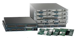
First, you need to rack and cable the equipment. For the correct way to install the equipment in the rack please check the Cisco UCS 5108 Server Chassis Installation Guide. In this guide, you can use pages 41-49 for the Chassis rack instructions and page 81 for the power cables needed. Then check the Cisco UCS 6200 Series Fabric Interconnect Hardware Installation Guide on pages 26 to 28. The next step would be to connect to the console port in the Fiber Interconnect (FI).

From the Guide (pp. 55-56):
- Plug the RJ-45 end of the serial management cable into the Console port on the fabric interconnect, and connect the DB-9 male end into the serial port on a laptop or other computer. If the computer you will use does not have a serial port, you will need to use the Serial to USB adapter. Be sure to install the drivers for your adapter.
- Start your terminal software.
- Configure the terminal software as follows:
- The COM port for the connection you are about to establish is the connection to the fabric interconnect. You may need to look in the computer’s device manager to confirm this. Example COM1 or COM5.
- The other connection parameters are 9600 baud, 8 data bits, no parity, 1 stop bit.
- Use the terminal software’s command to open the connection to the Fabric Interconnects. A session window will start, let’s take a look at the next to screenshots:
Figure 2. Fiber Interconnect Cluster Initial Configuration (FI-A)

Figure 3. Fiber Interconnect Cluster Initial Configuration (FI-B)

Now you are ready to connect to your UCS manager using your browser (Using the Cluster IPv4 address from the first screenshot).
Configure the Fiber Interconnect ports used to connect the Chassis as Server Ports. This will acknowledge the chassis and let you configure the rest.
Figure 4. Set the Chassis ports to Server Ports

I would like to show a few basic initial steps before we are ready to upgrade the firmware. After login into the UCS manager using your browser, change the Power Policy to “grid”. Equipment->Policies->Global Policies->Grid
Figure 4. Power Policy
The grid redundant configuration is sometimes used when you have two power sources to power a chassis or you require greater than N+1 redundancy. If one source fails (which causes a loss of power to one or two power supplies), the surviving power supplies on the other power circuit continue to provide power to the chassis. A common reason for using grid redundancy is if the rack power distribution is such that power is provided by two PDUs and you want the grid redundancy protection in the case of a PDU failure.
Another set of basic configuration parameters: the Call Home, the NTP and the Timezone.
Figure 5. Call Home Setting (leave it off until everything has been configured)

Figure 6. NTP and Timezone Settings

In the next new blogs, I will discuss the rest of the steps for configuration.
Part II: Firmware Upgrade
Part III: Pools and Policies
Part IV: Service Profile Templates
Part V: Storage

Leave a comment