Category: Cisco

  • Objective 2.03 Explain the purpose, use, and advantages of iApps.

    A. Explain the purpose of iApps

    F5 iApps is a powerful set of features in the BIG-IP system that provides 
a new way to architect application delivery in the data center. It gives you a holistic, application-centric view of how applications are managed and delivered inside, outside, and beyond the data center.
    By managing application services rather than the individual networking components and configurations, you can dramatically speed up deployment, lower OpEx, and streamline IT operations. You can provision application services in minutes rather than weeks, significantly improving time-to-market and creating a highly efficient and predictable process for successful application delivery.

    B. Explain the Advantages of iApps

    iApps provides a framework that application, security, network, systems, and operations personnel can use to unify, simplify, and control the entire Application Delivery Network (ADN). You gain a contextual view and advanced statistics about the application services supporting the business. iApps abstracts the many individual components required to
 deliver an application by grouping these resources together in templates associated with applications. This alleviates the need to manage discrete components on the network.

  • Objective 2.02 Explain the purpose use and advantages of iRules

    A. Explain the purpose of iRules

    F5 iRules is a flexible, programmatic interface that makes it possible to extend and customize the functionality of the BIG-IP system. As an event-driven scripting language, iRules gives you the ability to architect application delivery solutions that improve the security, resiliency, and scale of applications in the data center.

    B. Explain the Advantages of iRules

    iRules provides unprecedented control to directly manipulate and manage any IP application traffic using an easy-to-learn scripting syntax. A robust and active community at F5 DevCentralprovides a wealth of existing iRules that can be customized to fit your unique application requirements. With free registration on DevCentral, you have access to hundreds of proven iRules that can mitigate threats and extend the capabilities of your application delivery network. 
  • Objective 2.01 Articulate the role of F5 products.

    Explain the purpose use and benefits of:

    APM

    BIG-IP Access Policy Manager (APM) is a flexible, high-performance access and security solution that provides unified global access to your applications and network. By converging and consolidating remote access, LAN access, and wireless connections within a single management interface, and providing easy-to-manage access policies, BIG-IP APM helps you free up valuable IT resources and scale cost-effectively

    Key benefits

    • Provide unified global access 
    Consolidate remote access, LAN access, and wireless connections in one interface.
    • Consolidate and simplify
    Replace web access proxy tiers and integrate with OAM, XenApp, and Exchange to reduce infrastructure and management costs.
    • Centralize access control 
    Gain a simplified, central point of control to manage access to applications by dynamically enforcing context-aware policies.
    • Ensure superior access and endpoint security 
    Protect your organization from data loss, virus infection, and rogue device access with comprehensive endpoint capabilities.
    • Obtain flexibility, high performance, and scalability 
    Support all of your users easily, quickly, and cost-effectively

    Big IP Access Policy Manager Overview
    Big Ip Access Policy Manager Datasheet
    Configuration Guide for BIG IP Access Policy Manager


    ASM

    F5 BIG-IP® Application Security Manager(ASM) is a flexible web application firewall that secures web applications in traditional, virtual, and private cloud environments. BIG-IP ASM helps secure applications against unknown vulnerabilities, and enables compliance for key regulatory mandates. BIG-IP ASM is a key part of the F5 application delivery firewall solution, which consolidates traffic management, network firewall, application access, DDoS protection, SSL inspection, and DNS security. 

    Key benefits

    • Ensure app security and availability
    Get comprehensive geolocation attack protection from layer 7 distributed denial of service (DDoS), SQL injection, and OWASP Top Ten attacks, and secure the latest interactive AJAX applications and JSON payloads.
    • Reduce costs and enable compliance
    Achieve security standards compliance with built-in application protection.
    • Get out-of-the-box app security policies
    Provide protection with pre-built rapid deployment policies and minimal configuration.
    • Improve app security and performance
    Enable advanced application security while accelerating performance and improving cost effectiveness.
    • Deploy flexibly and incorporate external intelligence
    Focus on fast application development and flexible deployment in virtual and cloud environments while incorporating external intelligence for securing apps against IP threats.


    LTM

    F5® BIG-IP® Local Traffic Manager(LTM) helps you deliver your applications to your users, in a reliable, secure, and optimized way. You get the extensibility and flexibility of an intelligent services framework with the programmability you need to manage your physical, virtual, and cloud infrastructure. With BIG-IP LTM, you have the power to simplify, automate, and customize applications faster and more predictably.

    Key benefits

    • Deliver applications rapidly and reliably
    Ensure that your customers and users have access to the applications they need—whenever they need them.
    • Customize and automate with programmable infrastructure
    Control your applications—from connection and traffic to configuration and management—with
    F5’s unique TMOS. operating system, which includes native protocol support, an openmanagement
    API, and an event-driven scripting language.
    • Transition to SDN and cloud networks
    Realize operational consistency and comply with business needs across physical, virtual, and cloud environments with deployment flexibility and scalability.
    • Easily deploy and manage applications
    User-defined F5 iApps. Templates make it easy to deploy, manage, and get complete visibility into your applications.
    • Secure your critical applications
    Protect the apps that run your business with industry-leading SSL performance and visibility.


    GTM

    F5® BIG-IP® Global Traffic Manager™ (GTM) distributes DNS and user application requests based on business policies, data center and network conditions, user location, and application performance. BIG-IP GTM delivers F5’s high-performance DNS Services with visibility, reporting, and analysis; scales and secures DNS responses geographically to survive DDoS attacks; delivers a complete, real-time DNSSEC solution; and ensures global application high availability.

    Key benefits

    • Scale DNS to more than 10 million RPS with a fully-loaded chassis
    BIG IP GTM dramatically scales DNS to more than 10 million query RPS and controls DNS traffic. It ensures that users are connected to the best site, and delivers On-Demand Scaling for DNS and global apps
    • Gain control and secure global application delivery
    Route users based on business, geolocation, application, and network requirements to gain flexibility and control. Also ensure application availability and protection during DNS DDoS attacks or volume spikes.
    • Improve application performance
    Send users to the site with the best application performance based on application and network conditions. 
    • Deploy flexibly, scale as you grow, and manage your network efficiently
    BIG-IP GTM Virtual Edition (VE) delivers flexible global application management in virtual and cloud environments. Multiple management tools give you complete visibility and control; advanced logging, statistics and reporting; and a single point of control for your DNS and global app delivery resources.


    EM

     F5® Enterprise Manager™ significantly reduces the cost and complexity of managing multiple F5 devices. You gain a single-pane view of your entire application delivery infrastructure and the tools you need to automate common tasks, ensure optimized application performance, and improve budgeting and forecasting to meet changing business needs. Enterprise Manager is available as a physical or virtual edition. 

    Key benefits

    • Ensure optimized performance

    Get an up-to-date, comprehensive view of application traffic and device performance. Set thresholds and alerts to react quickly to changing network conditions and user demands.

    • Reduce TCO through automation

    Use a single interface to automate common operational tasks for your F5 devices, reducing total cost of ownership and OpEx.

    • Improve budgeting and forecasting

    Use 160 customizable metrics to gain complete visibility into your application delivery infrastructure over time and improve planning and budgeting for future projects.

    • Troubleshoot more effectively

    Quickly isolate application performance and traffic management problems to minimize the effect on your business.

    • Gain flexibility

    Deploy according to your business needs with the flexibility of physical and virtual Enterprise Manager editions
    Application-Delivery-Network-Platform-Management-White-Paper


    WA (Web Accelerator) 

    BIG-IP® WebAccelerator™ automates web performance optimization, to instantly improve performance for end users and help you reduce costs. By offloading your network and servers, BIG-IP WebAccelerator decreases your spending on additional bandwidth and hardware. Users get fast access to applications, and you gain greater revenue and free up IT resources for other strategic projects.

    WA Key benefits

    • Improve user experience and revenue 

    Reduce frustration for employees and consumers using your site with fast apps, and pave the way for higher productivity and sales.

    • Deploy according to your business needs

    Improve asymmetric deployment performance by 2x to 5x, and symmetric deployment by up to 10x. 

    • Reduce costs

    Reduce the number of application servers required with SSL offload, compression offload, and caching—and save both CapEx and OpEx.

    • Optimize server and bandwidth usage

    Extend server capacity and reduce bandwidth usage to improve performance and reduce costs.

    • Simplify deployment and management

    Use pre-defined policies for apps such as SharePoint, SAP Portal, Oracle Portal, E-business Suite 11/12, Siebel CRM, and more to simplify configuration.

    • Boost performance of mobile apps

    Apply front-end optimization techniques to overcome the unique app delivery challenges of mobile devices.
    Big-Ip-Webaccelerator-Overview
    Big-Ip-Webaccelerator-Data-Sheet
    Configuration-Guide-for-the-BIG-IP-WebAccelerator-System
    Policy-Management-Guide-for-the-BIG-IP-WebAccelerator-System


    WOM (Wan Optimization)

    F5® BIG-IP® WAN Optimization Module™ (WOM) compresses, deduplicates, and encrypts data between two data centers. When used in conjunction with Oracle Data Guard, BIG-IP WOM improves the performance of replication while enabling the secure transfer of data within your database management system (DBMS). The more latency, congestion, and packet loss your connection suffers from, the more BIG-IP WOM improves your replication environment.

    Key features

    • TCP Optimization—Cut down on the overhead inherent in TCP to speed replication
    • Rate Shaping—Set limits for how much and how little bandwidth Data Guard should receive
    • Compression—Send compressed versions of data over the WAN to reduce bandwidth
    • Deduplication—Send each distinct bit of data only once with advanced deduplication technology

    Key benefits

    • Increase Performance—Improve RPOs and RTOs by reducing data replication lag
    • Increase Efficiency—Maximize bandwidth utilization
    • Cost Savings—Reduce WAN costs and offload CPU-intensive processes from servers
    • Improve Security—Encrypt SQL transactions over the WAN

    Oracle-Data-Guard-Wom-Solution-Profile

    ARX

    F5 ARX intelligent file virtualization simplifies how your file data is accessed, moved, and managed. Data management policies help you match the business value of your data to the cost of its storage. Smart storage tiering moves your files automatically and without disruption or downtime, while dynamic capacity balancing improves overall utilization of your existing storage resources. ARX is available in a range of hardware devices and as a virtual edition.

    Key benefits
    • Reduce storage costs
    Match the business value of your data to the cost of its storage; reduce costs with new technologies.
    • Optimize backups
    Decrease the backup of redundant data to lower backup and recovery times, media consumption, and costs.
    • Maximize value of existing storage
    Improve utilization, reclaim stranded capacity, and defer additional storage purchases.
    • Simplify management
    Perform storage provisioning and decommissioning without disrupting users.
    • Improve flexibility and choice
    Move your data wherever and whenever you want, even between heterogeneous devices.
  • Objective 1.05 Explain the features and functionality of protocols and technologies specific to the application layer

    A. Explain the purpose and functionality of HTTP

    The Hypertext Transfer Protocol (HTTP) is an application protocol for distributed, collaborative, hypermedia information systems.[1] HTTP is the foundation of data communication for the World Wide Web.
    Hypertext is structured text that uses logical links (hyperlinks) between nodes containing text. HTTP is the protocol to exchange or transfer hypertext.
    The standards development of HTTP was coordinated by the Internet Engineering Task Force (IETF) and the World Wide Web Consortium (W3C), culminating in the publication of a series of Requests for Comments (RFCs), most notably RFC 2616 (June 1999), which defines HTTP/1.1, the version of HTTP in common use.
    HTTP functions as a request-response protocol in the client-server computing model. A web browser, for example, may be the client and an application running on a computer hosting a web site may be the server. The client submits an HTTP request message to the server. The server, which provides resources such asHTML files and other content, or performs other functions on behalf of the client, returns a response message to the client. The response contains completion status information about the request and may also contain requested content in its message body.
    A web browser is an example of a user agent (UA). Other types of user agent include the indexing software used by search providers (web crawlers), voice browsersmobile apps and other software that accesses, consumes or displays web content.
    HTTP is designed to permit intermediate network elements to improve or enable communications between clients and servers. High-traffic websites often benefit from web cache servers that deliver content on behalf of upstream servers to improve response time. Web browsers cache previously accessed web resources and reuse them when possible to reduce network traffic. HTTP proxy servers at private network boundaries can facilitate communication for clients without a globally routable address, by relaying messages with external servers.
    HTTP is an application layer protocol designed within the framework of the Internet Protocol Suite. Its definition presumes an underlying and reliable transport layerprotocol,[2] and Transmission Control Protocol (TCP) is commonly used. However HTTP can use unreliable protocols such as the User Datagram Protocol (UDP), for example in Simple Service Discovery Protocol (SSDP).
    HTTP resources are identified and located on the network by Uniform Resource Identifiers (URIs)—or, more specifically, Uniform Resource Locators (URLs)—using the http or https URI schemes. URIs and hyperlinks in Hypertext Markup Language (HTML) documents form webs of inter-linked hypertext documents.

    B. Differentiate between HTTP versions

    HTTP/1.1 is a revision of the original HTTP (HTTP/1.0). In HTTP/1.0 a separate connection to the same server is made for every resource request. HTTP/1.1 can reuse a connection multiple times to download images, scripts, stylesheets et cetera after the page has been delivered. HTTP/1.1 communications therefore experience less latency as the establishment of TCP connections presents considerable overhead.

    Goals for HTTP 2.0 include asynchronous connection multiplexing, header compression, and request-response pipelining, while maintaining full backwards compatibility with the transaction semantics of HTTP 1.1. It comes as an answer to the rise of SPDY, an HTTP compatible protocol launched by Google[2] and supported in ChromeOperaFirefox, and Amazon Silk browsers,[3] as well as the pressure from alternative protocols like WebSocket.
    The httpbis working group considered Google’s SPDY protocol, Microsoft‘s HTTP Speed+Mobility proposal (SPDY based),[4] and Network-Friendly HTTP Upgrade.[5] In July 2012 Facebook provided feedback on each of the proposals and recommended HTTP 2.0 be based on SPDY.[6] The initial draft of HTTP 2.0 was published in November 2012 and is based on a straight copy of SPDY.[7]
    Many of the architectural approaches in these protocols were explored earlier by the World Wide Web Consortium‘s HTTP-NG working group. Work on the HTTP-NG project was suspended in 1998.[8]

    C. Interpret HTTP status codes

    In HTTP/1.0 and since, the first line of the HTTP response is called the status line and includes a numeric status code (such as “404“) and a textual reason phrase (such as “Not Found”). The way the user agent handles the response primarily depends on the code and secondarily on the response headers. Custom status codes can be used since, if the user agent encounters a code it does not recognize, it can use the first digit of the code to determine the general class of the response.[20]
    Also, the standard reason phrases are only recommendations and can be replaced with “local equivalents” at the web developer‘s discretion. If the status code indicated a problem, the user agent might display the reason phrase to the user to provide further information about the nature of the problem. The standard also allows the user agent to attempt to interpret the reason phrase, though this might be unwise since the standard explicitly specifies that status codes are machine-readable and reason phrases are human-readable.

    1xx Informational[edit|edit source]

    Request received, continuing process.[2]
    This class of status code indicates a provisional response, consisting only of the Status-Line and optional headers, and is terminated by an empty line. Since HTTP/1.0 did not define any 1xx status codes, servers must not send a 1xx response to an HTTP/1.0 client except under experimental conditions.
    100 Continue
    This means that the server has received the request headers, and that the client should proceed to send the request body (in the case of a request for which a body needs to be sent; for example, aPOST request). If the request body is large, sending it to a server when a request has already been rejected based upon inappropriate headers is inefficient. To have a server check if the request could be accepted based on the request’s headers alone, a client must send Expect: 100-continue as a header in its initial request[2] and check if a 100 Continue status code is received in response before continuing (or receive 417 Expectation Failed and not continue).[2]
    101 Switching Protocols
    This means the requester has asked the server to switch protocols and the server is acknowledging that it will do so.[2]
    102 Processing (WebDAV; RFC 2518)
    As a WebDAV request may contain many sub-requests involving file operations, it may take a long time to complete the request. This code indicates that the server has received and is processing the request, but no response is available yet.[3] This prevents the client from timing out and assuming the request was lost.

    2xx Success[edit]

    This class of status codes indicates the action requested by the client was received, understood, accepted and processed successfully.
    200 OK
    Standard response for successful HTTP requests. The actual response will depend on the request method used. In a GET request, the response will contain an entity corresponding to the requested resource. In a POST request the response will contain an entity describing or containing the result of the action.[2]
    201 Created
    The request has been fulfilled and resulted in a new resource being created.[2]
    202 Accepted
    The request has been accepted for processing, but the processing has not been completed. The request might or might not eventually be acted upon, as it might be disallowed when processing actually takes place.[2]
    203 Non-Authoritative Information (since HTTP/1.1)
    The server successfully processed the request, but is returning information that may be from another source.[2]
    204 No Content
    The server successfully processed the request, but is not returning any content.[2] Usually used as a response to a successful delete request.
    205 Reset Content
    The server successfully processed the request, but is not returning any content. Unlike a 204 response, this response requires that the requester reset the document view.[2]
    206 Partial Content
    The server is delivering only part of the resource due to a range header sent by the client. The range header is used by tools like wget to enable resuming of interrupted downloads, or split a download into multiple simultaneous streams.[2]
    207 Multi-Status (WebDAV; RFC 4918)
    The message body that follows is an XML message and can contain a number of separate response codes, depending on how many sub-requests were made.[4]
    208 Already Reported (WebDAV; RFC 5842)
    The members of a DAV binding have already been enumerated in a previous reply to this request, and are not being included again.
    226 IM Used (RFC 3229)
    The server has fulfilled a GET request for the resource, and the response is a representation of the result of one or more instance-manipulations applied to the current instance.[5]

    3xx Redirection[edit]

    The client must take additional action to complete the request.[2]
    This class of status code indicates that further action needs to be taken by the user agent to fulfil the request. The action required may be carried out by the user agent without interaction with the user if and only if the method used in the second request is GET or HEAD. A user agent should not automatically redirect a request more than five times, since such redirections usually indicate an infinite loop.
    300 Multiple Choices
    Indicates multiple options for the resource that the client may follow. It, for instance, could be used to present different format options for video, list files with different extensions, or word sense disambiguation.[2]
    301 Moved Permanently
    This and all future requests should be directed to the given URI.[2]
    302 Found
    This is an example of industry practice contradicting the standard.[2] The HTTP/1.0 specification (RFC 1945) required the client to perform a temporary redirect (the original describing phrase was “Moved Temporarily”),[6] but popular browsers implemented 302 with the functionality of a 303 See Other. Therefore, HTTP/1.1 added status codes 303 and 307 to distinguish between the two behaviours.[7]However, some Web applications and frameworks use the 302 status code as if it were the 303.[8]
    303 See Other (since HTTP/1.1)
    The response to the request can be found under another URI using a GET method. When received in response to a POST (or PUT/DELETE), it should be assumed that the server has received the data and the redirect should be issued with a separate GET message.[2]
    304 Not Modified
    Indicates that the resource has not been modified since the version specified by the request headers If-Modified-Since or If-Match.[2] This means that there is no need to retransmit the resource, since the client still has a previously-downloaded copy.
    305 Use Proxy (since HTTP/1.1)
    The requested resource is only available through a proxy, whose address is provided in the response.[2] Many HTTP clients (such as Mozilla[9] and Internet Explorer) do not correctly handle responses with this status code, primarily for security reasons.[citation needed]
    306 Switch Proxy
    No longer used.[2] Originally meant “Subsequent requests should use the specified proxy.”[10]
    307 Temporary Redirect (since HTTP/1.1)
    In this case, the request should be repeated with another URI; however, future requests should still use the original URI.[2] In contrast to how 302 was historically implemented, the request method is not allowed to be changed when reissuing the original request. For instance, a POST request should be repeated using another POST request.[11]
    308 Permanent Redirect (approved as experimental RFC)[12]
    The request, and all future requests should be repeated using another URI. 307 and 308 (as proposed) parallel the behaviours of 302 and 301, but do not allow the HTTP method to change. So, for example, submitting a form to a permanently redirected resource may continue smoothly.

    4xx Client Error[edit]

    The 4xx class of status code is intended for cases in which the client seems to have erred. Except when responding to a HEAD request, the server should include an entity containing an explanation of the error situation, and whether it is a temporary or permanent condition. These status codes are applicable to any request method. User agents should display any included entity to the user.
    400 Bad Request
    The request cannot be fulfilled due to bad syntax.[2]
    401 Unauthorized
    Similar to 403 Forbidden, but specifically for use when authentication is required and has failed or has not yet been provided.[2] The response must include a WWW-Authenticate header field containing a challenge applicable to the requested resource. See Basic access authentication and Digest access authentication.
    402 Payment Required
    Reserved for future use.[2] The original intention was that this code might be used as part of some form of digital cash or micropayment scheme, but that has not happened, and this code is not usually used. As an example of its use, however, Apple’s defunct MobileMe service generated a 402 error if the MobileMe account was delinquent.[citation needed] In addition, YouTube uses this status if a particular IP address has made excessive requests, and requires the person to enter a CAPTCHA.
    403 Forbidden
    The request was a valid request, but the server is refusing to respond to it.[2] Unlike a 401 Unauthorized response, authenticating will make no difference.[2] On servers where authentication is required, this commonly means that the provided credentials were successfully authenticated but that the credentials still do not grant the client permission to access the resource (e.g. a recognized user attempting to access restricted content).
    404 Not Found
    The requested resource could not be found but may be available again in the future.[2] Subsequent requests by the client are permissible.
    405 Method Not Allowed
    A request was made of a resource using a request method not supported by that resource;[2] for example, using GET on a form which requires data to be presented via POST, or using PUT on a read-only resource.
    406 Not Acceptable
    The requested resource is only capable of generating content not acceptable according to the Accept headers sent in the request.[2]
    407 Proxy Authentication Required
    The client must first authenticate itself with the proxy.[2]
    408 Request Timeout
    The server timed out waiting for the request.[2] According to W3 HTTP specifications: “The client did not produce a request within the time that the server was prepared to wait. The client MAY repeat the request without modifications at any later time.”
    409 Conflict
    Indicates that the request could not be processed because of conflict in the request, such as an edit conflict in the case of multiple updates.[2]
    410 Gone
    Indicates that the resource requested is no longer available and will not be available again.[2] This should be used when a resource has been intentionally removed and the resource should be purged. Upon receiving a 410 status code, the client should not request the resource again in the future. Clients such as search engines should remove the resource from their indices. Most use cases do not require clients and search engines to purge the resource, and a “404 Not Found” may be used instead.
    411 Length Required
    The request did not specify the length of its content, which is required by the requested resource.[2]
    412 Precondition Failed
    The server does not meet one of the preconditions that the requester put on the request.[2]
    413 Request Entity Too Large
    The request is larger than the server is willing or able to process.[2]
    414 Request-URI Too Long
    The URI provided was too long for the server to process.[2] Often the result of too much data being encoded as a query-string of a GET request, in which case it should be converted to a POST request.
    415 Unsupported Media Type
    The request entity has a media type which the server or resource does not support.[2] For example, the client uploads an image as image/svg+xml, but the server requires that images use a different format.
    416 Requested Range Not Satisfiable
    The client has asked for a portion of the file, but the server cannot supply that portion.[2] For example, if the client asked for a part of the file that lies beyond the end of the file.[2]
    417 Expectation Failed
    The server cannot meet the requirements of the Expect request-header field.[2]
    418 I’m a teapot (RFC 2324)
    This code was defined in 1998 as one of the traditional IETF April Fools’ jokes, in RFC 2324Hyper Text Coffee Pot Control Protocol, and is not expected to be implemented by actual HTTP servers.
    419 Authentication Timeout (not in RFC 2616)
    Not a part of the HTTP standard, 419 Authentication Timeout denotes that previously valid authentication has expired. It is used as an alternative to 401 Unauthorized in order to differentiate from otherwise authenticated clients being denied access to specific server resources.
    420 Enhance Your Calm (Twitter)
    Not part of the HTTP standard, but returned by the Twitter Search and Trends API when the client is being rate limited.[13] Other services may wish to implement the 429 Too Many Requests response code instead.
    422 Unprocessable Entity (WebDAV; RFC 4918)
    The request was well-formed but was unable to be followed due to semantic errors.[4]
    423 Locked (WebDAV; RFC 4918)
    The resource that is being accessed is locked.[4]
    424 Failed Dependency (WebDAV; RFC 4918)
    The request failed due to failure of a previous request (e.g. a PROPPATCH).[4]
    424 Method Failure (WebDAV)[14]
    Indicates the method was not executed on a particular resource within its scope because some part of the method’s execution failed causing the entire method to be aborted.
    425 Unordered Collection (Internet draft)
    Defined in drafts of “WebDAV Advanced Collections Protocol”,[15] but not present in “Web Distributed Authoring and Versioning (WebDAV) Ordered Collections Protocol”.[16]
    426 Upgrade Required (RFC 2817)
    The client should switch to a different protocol such as TLS/1.0.[17]
    428 Precondition Required (RFC 6585)
    The origin server requires the request to be conditional. Intended to prevent “the ‘lost update’ problem, where a client GETs a resource’s state, modifies it, and PUTs it back to the server, when meanwhile a third party has modified the state on the server, leading to a conflict.”[18]
    429 Too Many Requests (RFC 6585)
    The user has sent too many requests in a given amount of time. Intended for use with rate limiting schemes.[18]
    431 Request Header Fields Too Large (RFC 6585)
    The server is unwilling to process the request because either an individual header field, or all the header fields collectively, are too large.[18]
    444 No Response (Nginx)
    Used in Nginx logs to indicate that the server has returned no information to the client and closed the connection (useful as a deterrent for malware).
    449 Retry With (Microsoft)
    A Microsoft extension. The request should be retried after performing the appropriate action.[19]
    Often search-engines or custom applications will ignore required parameters. Where no default action is appropriate, the Aviongoo website sends a “HTTP/1.1 449 Retry with valid parameters: param1, param2, . . .” response. The applications may choose to learn, or not.
    450 Blocked by Windows Parental Controls (Microsoft)
    A Microsoft extension. This error is given when Windows Parental Controls are turned on and are blocking access to the given webpage.[20]
    451 Unavailable For Legal Reasons (Internet draft)
    Defined in the internet draft “A New HTTP Status Code for Legally-restricted Resources”.[21] Intended to be used when resource access is denied for legal reasons, e.g. censorship or government-mandated blocked access. A reference to the 1953 dystopian novel Fahrenheit 451, where books are outlawed.[22]
    451 Redirect (Microsoft)
    Used in Exchange ActiveSync if there either is a more efficient server to use or the server can’t access the users’ mailbox.[23]
    The client is supposed to re-run the HTTP Autodiscovery protocol to find a better suited server.[24]
    494 Request Header Too Large (Nginx)
    Nginx internal code similar to 413 but it was introduced earlier.[25][original research?]
    495 Cert Error (Nginx)
    Nginx internal code used when SSL client certificate error occurred to distinguish it from 4XX in a log and an error page redirection.
    496 No Cert (Nginx)
    Nginx internal code used when client didn’t provide certificate to distinguish it from 4XX in a log and an error page redirection.
    497 HTTP to HTTPS (Nginx)
    Nginx internal code used for the plain HTTP requests that are sent to HTTPS port to distinguish it from 4XX in a log and an error page redirection.
    499 Client Closed Request (Nginx)
    Used in Nginx logs to indicate when the connection has been closed by client while the server is still processing its request, making server unable to send a status code back.[26]

    5xx Server Error[edit]

    The server failed to fulfill an apparently valid request.[2]
    Response status codes beginning with the digit “5” indicate cases in which the server is aware that it has encountered an error or is otherwise incapable of performing the request. Except when responding to a HEAD request, the server should include an entity containing an explanation of the error situation, and indicate whether it is a temporary or permanent condition. Likewise, user agents should display any included entity to the user. These response codes are applicable to any request method.
    500 Internal Server Error
    A generic error message, given when no more specific message is suitable.[2]
    501 Not Implemented
    The server either does not recognize the request method, or it lacks the ability to fulfill the request.[2] Usually this implies future availability (eg. a new feature of a web-service API).
    502 Bad Gateway
    The server was acting as a gateway or proxy and received an invalid response from the upstream server.[2]
    503 Service Unavailable
    The server is currently unavailable (because it is overloaded or down for maintenance).[2] Generally, this is a temporary state.
    504 Gateway Timeout
    The server was acting as a gateway or proxy and did not receive a timely response from the upstream server.[2]
    505 HTTP Version Not Supported
    The server does not support the HTTP protocol version used in the request.[2]
    506 Variant Also Negotiates (RFC 2295)
    Transparent content negotiation for the request results in a circular reference.[27]
    507 Insufficient Storage (WebDAV; RFC 4918)
    The server is unable to store the representation needed to complete the request.[4]
    508 Loop Detected (WebDAV; RFC 5842)
    The server detected an infinite loop while processing the request (sent in lieu of 208).
    509 Bandwidth Limit Exceeded (Apache bw/limited extension)
    This status code, while used by many servers, is not specified in any RFCs.
    510 Not Extended (RFC 2774)
    Further extensions to the request are required for the server to fulfil it.[28]
    511 Network Authentication Required (RFC 6585)
    The client needs to authenticate to gain network access. Intended for use by intercepting proxies used to control access to the network (e.g. “captive portals” used to require agreement to Terms of Service before granting full Internet access via a Wi-Fi hotspot).[18]
    598 Network read timeout error (Unknown)
    This status code is not specified in any RFCs, but is used by Microsoft HTTP proxies to signal a network read timeout behind the proxy to a client in front of the proxy.[citation needed]
    599 Network connect timeout error (Unknown)
    This status code is not specified in any RFCs, but is used by Microsoft HTTP proxies to signal a network connect timeout behind the proxy to a client in front of the proxy.

    D. Determine an HTTP request method for a given use case

    HTTP defines methods (sometimes referred to as verbs) to indicate the desired action to be performed on the identified resource. What this resource represents, whether pre-existing data or data that is generated dynamically, depends on the implementation of the server. Often, the resource corresponds to a file or the output of an executable residing on the server.
    The HTTP/1.0 specification[10]:section 8 defined the GET, POST and HEAD methods and the HTTP/1.1 specification[1]:section 9 added 5 new methods: OPTIONS, PUT, DELETE, TRACE and CONNECT. By being specified in these documents their semantics are well known and can be depended upon. Any client can use any method and the server can be configured to support any combination of methods. If a method is unknown to an intermediate it will be treated as an unsafe and non-idempotent method. There is no limit to the number of methods that can be defined and this allows for future methods to be specified without breaking existing infrastructure. For example WebDAV defined 7 new methods and RFC5789 specified the PATCH method.
    GET
    Requests a representation of the specified resource. Requests using GET should only retrieve data and should have no other effect. (This is also true of some other HTTP methods.)[1] The W3C has published guidance principles on this distinction, saying, “Web application design should be informed by the above principles, but also by the relevant limitations.”[11] See safe methods below.
    HEAD
    Asks for the response identical to the one that would correspond to a GET request, but without the response body. This is useful for retrieving meta-information written in response headers, without having to transport the entire content.
    POST 
    Requests that the server accept the entity enclosed in the request as a new subordinate of the web resource identified by the URI. The data POSTed might be, as examples, an annotation for existing resources; a message for a bulletin board, newsgroup, mailing list, or comment thread; a block of data that is the result of submitting a web form to a data-handling process; or an item to add to a database.[12]
    PUT
    Requests that the enclosed entity be stored under the supplied URI. If the URI refers to an already existing resource, it is modified; if the URI does not point to an existing resource, then the server can create the resource with that URI.[13]
    DELETE
    Deletes the specified resource.
    TRACE
    Echoes back the received request so that a client can see what (if any) changes or additions have been made by intermediate servers.
    OPTIONS
    Returns the HTTP methods that the server supports for specified URL. This can be used to check the functionality of a web server by requesting ‘*’ instead of a specific resource.
    CONNECT
    Converts the request connection to a transparent TCP/IP tunnel, usually to facilitate SSL-encrypted communication (HTTPS) through an unencrypted HTTP proxy.[14][15]
    PATCH
    Is used to apply partial modifications to a resource.[16]
    HTTP servers are required to implement at least the GET and HEAD methods[17] and, whenever possible, also the OPTIONS method.

    E. Explain the purpose and functionality of HTTP keepalives

    Persistent connections[edit]

    In HTTP/0.9 and 1.0, the connection is closed after a single request/response pair. In HTTP/1.1 a keep-alive-mechanism was introduced, where a connection could be reused for more than one request. Such persistent connections reduce request latency perceptibly, because the client does not need to re-negotiate the TCP connection after the first request has been sent. Another positive side effect is that in general the connection becomes faster with time due to TCP’s slow-start-mechanism.
    Version 1.1 of the protocol also made bandwidth optimization improvements to HTTP/1.0. For example, HTTP/1.1 introduced chunked transfer encoding to allow content on persistent connections to be streamed rather than buffered. HTTP pipelining further reduces lag time, allowing clients to send multiple requests before waiting for each response. Another improvement to the protocol was byte serving, where a server transmits just the portion of a resource explicitly requested by a client.

    HTTP session state[edit]

    HTTP is a stateless protocol. A stateless protocol does not require the HTTP server to retain information or status about each user for the duration of multiple requests. However, some web applicationsimplement states or server side sessions using one or more of the following methods:


    F. Explain the purpose and functionality of HTTP headers

    HTTP header fields are components of the message header of requests and responses in the Hypertext Transfer Protocol (HTTP). They define the operating parameters of an HTTP transaction. The header fields are transmitted after the request or response line, which is the first line of a message. Header fields are colon-separated name-value pairs in clear-text string format, terminated by a carriage return (CR) and line feed (LF) character sequence. The end of the header fields is indicated by an empty field, resulting in the transmission of two consecutive CR-LF pairs. Long lines can be folded into multiple lines; continuation lines are indicated by the presence of a space (SP) or horizontal tab (HT) as the first character on the next line.

    G. Explain the purpose and functionality of DNS

    The Domain Name System (DNS) is a hierarchical distributed naming system for computers, services, or any resource connected to the Internet or a private network. It associates various information with domain names assigned to each of the participating entities. Most prominently, it translates easily memorizeddomain names to the numerical IP addresses needed for the purpose of locating computer services and devices worldwide. By providing a worldwide, distributedkeyword-based redirection service, the Domain Name System is an essential component of the functionality of the Internet.

    H. Explain the purpose and functionality of SIP

    The Session Initiation Protocol (SIP) is a signaling communications protocol, widely used for controlling multimedia communication sessions such as voiceand video calls over Internet Protocol (IP) networks.
    The protocol defines the messages that are sent between peers which govern establishment, termination and other essential elements of a call. SIP can be used for creating, modifying and terminating two-party (unicast) or multiparty (multicastsessions consisting of one or several media streams. Other SIP applications include video conferencing, streaming multimedia distribution, instant messagingpresence informationfile transferfax over IP and online games.
    Originally designed by Henning Schulzrinne and Mark Handley in 1996, SIP has been developed and standardized in RFC 3261 under the auspices of theInternet Engineering Task Force (IETF). It is an application layer protocol designed to be independent of the underlying transport layer; it can run on Transmission Control Protocol (TCP), User Datagram Protocol (UDP) or Stream Control Transmission Protocol (SCTP).[1] It is a text-based protocol, incorporating many elements of the Hypertext Transfer Protocol (HTTP) and the Simple Mail Transfer Protocol (SMTP).[2]
    SIP works in conjunction with several other application layer protocols that identify and carry the session media. Media identification and negotiation is achieved with the Session Description Protocol (SDP). For the transmission of media streams (voice, video) SIP typically employs the Real-time Transport Protocol (RTP), which may be secured with the Secure Real-time Transport Protocol (SRTP). For secure transmissions of SIP messages the protocol may be encrypted withTransport Layer Security (TLS).

    I. Explain the purpose and functionality of FTP

    File Transfer Protocol (FTP) is a standard network protocol used to transfer files from one host to another host over a TCP-based network, such as the Internet.
    FTP is built on a client-server architecture and uses separate control and data connections between the client and the server.[1] FTP users may authenticate themselves using a clear-text sign-in protocol, normally in the form of a username and password, but can connect anonymously if the server is configured to allow it. For secure transmission that hides (encrypts) the username and password, and encrypts the content, FTP is often secured with SSL/TLS (“FTPS”). SSH File Transfer Protocol (“SFTP”) is sometimes also used instead, but is technologically different.
    The first FTP client applications were command-line applications developed before operating systems had graphical user interfaces, and are still shipped with most WindowsUnix, and Linux operating systems.[2][3] Dozens of FTP clients and automation utilities have since been developed for desktops, servers, mobile devices, and hardware, and FTP has been incorporated into hundreds of productivity applications, such as Web page editors.

    J. Differentiate between passive and active FTP

    FTP may run in active or passive mode, which determines how the data connection is established. In active mode, the client creates a TCP control connection. In situations where the client is behind a firewall and unable to accept incoming TCP connections, passive mode may be used. In this mode, the client uses the control connection to send a PASV command to the server and then receives a server IP address and server port number from the server, which the client then uses to open a data connection from an arbitrary client port to the server IP address and server port number received. Both modes were updated in September 1998 to support IPv6. Further changes were introduced to the passive mode at that time, updating it to extended passive mode.
    K. Explain the purpose and functionality of SMTP

    Simple Mail Transfer Protocol (SMTP) is an Internet standard for electronic mail (e-mail) transmission across Internet Protocol (IP) networks. SMTP was first defined by RFC 821 (1982, eventually declared STD 10),[1] and last updated by RFC 5321 (2008)[2] which includes the Extended SMTP (ESMTP) additions, and is the protocol in widespread use today.
    SMTP uses TCP port 25. The protocol for new submissions (MSA) is effectively the same as SMTP, but it uses port 587 instead. SMTP connections secured bySSL are known by the shorthand SMTPS, though SMTPS is not a protocol in its own right.
    While electronic mail servers and other mail transfer agents use SMTP to send and receive mail messages, user-level client mail applications typically use SMTP only for sending messages to a mail server for relaying. For receiving messages, client applications usually use either the Post Office Protocol (POP) or the Internet Message Access Protocol (IMAP) or a proprietary system (such as Microsoft Exchange or Lotus Notes/Domino) to access their mail box accounts on a mail server.

    L. Explain the purpose and functionality of a cookie

    cookie, also known as an HTTP cookieweb cookie, or browser cookie, is a small piece of data sent from a website and stored in a user’s web browserwhile a user is browsing a website. When the user browses the same website in the future, the data stored in the cookie is sent back to the website by the browser to notify the website of the user’s previous activity.[1] Cookies were designed to be a reliable mechanism for websites to remember the state of the website or activity the user had taken in the past. This can include clicking particular buttons, logging in, or a record of which pages were visited by the user even months or years ago.
    Although cookies cannot carry viruses, and cannot install malware on the host computer,[2] tracking cookies and especially third-party tracking cookies are commonly used as ways to compile long-term records of individuals’ browsing histories—a potential privacy concern that prompted European and US law makers to take action in 2011.[3][4] Cookies can also store passwords and forms a user has previously entered, such as a credit card number or an address. When a user accesses a website with a cookie function for the first time, a cookie is sent from server to the browser and stored with the browser in the local computer. Later when that user goes back to the same website, the website will recognize the user because of the stored cookie with the user’s information.[5]
    Other kinds of cookies perform essential functions in the modern web. Perhaps most importantly, authentication cookies are the most common method used by web servers to know whether the user is logged in or not, and which account they are logged in under. Without such a mechanism, the site would not know whether to send a page containing sensitive information, or require the user to authenticate himself by logging in. The security of an authentication cookie generally depends on the security of the issuing website and the user’s web browser, and on whether the cookie data is encrypted. Security vulnerabilities may allow a cookie’s data to be read by a hacker, used to gain access to user data, or used to gain access (with the user’s credentials) to the website to which the cookie belongs (see cross-site scripting and cross-site request forgery for examples).

    M. Given a situation in which a client connects to a remote host, explain how the name resolution process occurs

    DNS Name Resolution Process 

    Resolution Process Steps
    Now, suppose you are an employee within XYZ Industries and one of your clients is in charge of the networking department at Googleplex U. You type into your Web browser the address of this department’s Web server, “www.net.compsci.googleplex.edu”. In simplified terms, the procedure would involve the following set of steps (Figure 245 shows the process graphically):
    1. Your Web browser recognizes the request for a name and invokes your local resolver, passing to it the name “www.net.compsci.googleplex.edu”.
    2. The resolver checks its cache to see if it already has the address for this name. If it does, it returns it immediately to the Web browser, but in this case we are assuming that it does not. The resolver also checks to see if it has a local host table file. If so, it scans the file to see if this name has a static mapping. If so, it resolves the name using this information immediately. Again, let’s assume it does not, since that would be boring.
    3. The resolver generates a recursive query and sends it to “ns1.xyzindustries.com” (using that server’s IP address, of course, which the resolver knows).
    4. The local DNS server receives the request and checks its cache. Again, let’s assume it doesn’t have the information needed. If it did, it would return the information, marked “non-authoritative”, to the resolver. The server also checks to see if it has in its zone resource records that can resolve “www.net.compsci.googleplex.edu”. Of course it does not, in this case, since they are in totally different domains.
    5. “ns1.xyzindustries.com” generates an iterative request for the name and sends it to a root name server.
    6. The root name server does not resolve the name. It returns the name and address of the name server for the “.edu” domain. 
    7. “ns1.xyzindustries.com” generates an iterative request and sends it to the name server for “.edu”.
    8. The name server for “.edu” returns the name and address of the name server for the “googleplex.edu” domain.
    9. “ns1.xyzindustries.com” generates an iterative request and sends it to the name server for “googleplex.edu”.
    10. The name server for “googleplex.edu” consults its resource records. It sees, however, that this name is in the “compsci.googleplex.edu” subdomain, which is in a separate zone. It returns the name server for that zone.
    11. “ns1.xyzindustries.com” generates an iterative request and sends it to the name server for “compsci.googleplex.edu”.
    12. The name server for “compsci.googleplex.edu” is authoritative for “www.net.compsci.googleplex.edu”. It returns the IP address for that host to “ns1.xyzindustries.com”.
    13. “ns1.xyzindustries.com” caches this resolution. (Note that it will probably also cache some of the other name server resolutions that it received in steps #6, #8 and #10; I have not shown these explicitly.)
    14. The local name server returns the resolution to the resolver on your local machine.
    15. Your local resolver also caches the information.
    16. The local resolver gives the address to your browser.
    17. Your browser commences an HTTP request to the Googleplex machine’s IP address.
      Figure 245: Example Of The DNS Name Resolution Process
      This fairly complex example illustrates a typical DNS name resolution using both iterative and recursive resolution. The user types in a DNS name (“www.net.compsci.googleplex.edu”) into a Web browser, which causes a DNS resolution request to be made from her client machine’s resolver to a local DNS name server. That name server agrees to resolve the name recursively on behalf of the resolver, but uses iterative requests to accomplish it. These requests are sent to a DNS root name server, followed in turn by the name servers for “.edu”, “googleplex.edu” and ‘compsci.googleplex.edu”. The IP address is then passed to the local name server and then back to the user’s resolver and finally, her Web browser software.
    Seems rather complicated and slow. Of course, computers work faster than you can read (or I can type, for that matter.) Even given that, the benefits of caching are obvious—if the name was in the cache of the resolver or the local DNS server, most of these steps would be avoided.

      N. Explain the purpose and functionality of a URL

      uniform resource locator, abbreviated URL, also known as web address, is a specific character string that constitutes a reference to a resource. In most web browsers, the URL of a web page is displayed on top inside an address bar. An example of a typical URL would be http://en.example.org/wiki/Main_Page”. A URL is technically a type of uniform resource identifier (URI), but in many technical documents and verbal discussions, URL is often used as a synonym for URI, and this is not considered a problem.[1]
    • Objective 1.04 Explain the features and functionality of protocols and technologies specific to the transport layer

      A. Compare/Contrast purpose and functionality of MTU and MSS

      In computer networking, the maximum transmission unit (MTU) of a communications protocol of a layer is the size (in bytes) of the largest protocol data unit that the layer can pass onwards. MTU parameters usually appear in association with a communications interface (NICserial port, etc.). Standards (Ethernet, for example) can fix the size of an MTU; or systems (such as point-to-point serial links) may decide MTU at connect time.
      A larger MTU brings greater efficiency because each packet carries more user data while protocol overheads, such as headers or underlying per-packet delays, remain fixed; the resulting higher efficiency means a slight improvement in bulk protocol throughput. A larger MTU also means processing of fewer packets for the same amount of data. In some systems, per-packet-processing can be a critical performance limitation.
      However, this gain is not without some downside. Large packets can occupy a slow link for some time, causing greater delays to following packets and increasing lag and minimum latency. For example, a 1500-byte packet, the largest allowed by Ethernet at the network layer (and hence over most of the Internet), ties up a 14.4k modem for about one second.
      Large packets are also problematic in the presence of communications errors. Corruption of a single bit in a packet requires that the entire packet be retransmitted. At a given bit error rate, larger packets are more likely to be corrupted. Retransmissions of larger packets takes longer. Despite the negative effects on retransmission duration, large packets can still have a net positive effect on end-to-end TCP performance.
      The maximum segment size (MSS) is a parameter of the TCP protocol that specifies the largest amount of data, specified in octets, that a computer or communications device can receive in a single TCP segment, and therefore in a single IP datagram. It does not count the TCP header or the IP header.[1] The IP datagram containing a TCP segment may be self-contained within a single packet, or it may be reconstructed from several fragmented pieces; either way, the MSS limit applies to the total amount of data contained in the final, reconstructed TCP segment.
      Therefore: Headers + MSS ≤ MTU
      The Maximum segment size to avoid fragmentation = Largest datagram size that any host is required to be able to reassemble – IP header size – TCP header size
      So most IPv4 hosts are required to be able to handle an MSS of 536 octets (= 576 – 20 – 20)
      and most IPv6 hosts are required to be able to handle an MSS of 1220 octets (= 1280 – 40 – 20).[2]
      A lower MSS will ensure that fragmentation will never be done along the path but, in counterpart, the data/header ratio will be lower.
      For most computer users, the MSS option is established by the operating system on the SYN packet during the TCP handshake. Each direction of data flow can use a different MSS.

      B. Explain the purpose and functionality of TCP

      The Transmission Control Protocol (TCP) is one of the core protocols of the Internet protocol suite (IP), and is so common that the entire suite is often calledTCP/IP. TCP provides reliable, ordered, error-checked delivery of a stream of octets between programs running on computers connected to a local area network,intranet or the public Internet. It resides at the transport layer.

      TCP segment structure

      Transmission Control Protocol accepts data from a data stream, divides it into chunks, and adds a TCP header creating a TCP segment. The TCP segment is then encapsulated into an Internet Protocol (IP) datagram, and exchanged with peers. [3]
      The term TCP packet, though sometimes informally used, is not in line with current terminology, where segment refers to the TCP Protocol Data Unit (PDU)datagram[4] to the IP PDU and frame to the data link layer PDU:
      Processes transmit data by calling on the TCP and passing buffers of data as arguments. The TCP packages the data from these buffers into segments and calls on the internet module [e.g. IP] to transmit each segment to the destination TCP.[5]
      A TCP segment consists of a segment header and a data section. The TCP header contains 10 mandatory fields, and an optional extension field (Options, orange background in table).
      The data section follows the header. Its contents are the payload data carried for the application. The length of the data section is not specified in the TCP segment header. It can be calculated by subtracting the combined length of the TCP header and the encapsulating IP header from the total IP datagram length (specified in the IP header).
      TCP Header
      Offsets Octet 0 1 2 3
      Octet Bit  0  1  2  3  4  5  6  7  8  9 10 11 12 13 14 15 16 17 18 19 20 21 22 23 24 25 26 27 28 29 30 31
      0 0 Source port Destination port
      4 32 Sequence number
      8 64 Acknowledgment number (if ACK set)
      12 96 Data offset Reserved
      0 0 0
      N
      S
      C
      W
      R
      E
      C
      E
      U
      R
      G
      A
      C
      K
      P
      S
      H
      R
      S
      T
      S
      Y
      N
      F
      I
      N
      Window Size
      16 128 Checksum Urgent pointer (if URG set)
      20
      160
      ...
      Options (if data offset > 5. Padded at the end with “0” bytes if necessary.)
      Source port (16 bits)
      identifies the sending port
      Destination port (16 bits)
      identifies the receiving port
      Sequence number (32 bits)
      has a dual role:

      • If the SYN flag is set (1), then this is the initial sequence number. The sequence number of the actual first data byte and the acknowledged number in the corresponding ACK are then this sequence number plus 1.
      • If the SYN flag is clear (0), then this is the accumulated sequence number of the first data byte of this segment for the current session.
      Acknowledgment number (32 bits)
      if the ACK flag is set then the value of this field is the next sequence number that the receiver is expecting. This acknowledges receipt of all prior bytes (if any). The first ACK sent by each end acknowledges the other end’s initial sequence number itself, but no data.
      Data offset (4 bits)
      specifies the size of the TCP header in 32-bit words. The minimum size header is 5 words and the maximum is 15 words thus giving the minimum size of 20 bytes and maximum of 60 bytes, allowing for up to 40 bytes of options in the header. This field gets its name from the fact that it is also the offset from the start of the TCP segment to the actual data.
      Reserved (3 bits)
      for future use and should be set to zero
      Flags (9 bits) (aka Control bits)
      contains 9 1-bit flags

      • NS (1 bit) – ECN-nonce concealment protection (added to header by RFC 3540).
      • CWR (1 bit) – Congestion Window Reduced (CWR) flag is set by the sending host to indicate that it received a TCP segment with the ECE flag set and had responded in congestion control mechanism (added to header by RFC 3168).
      • ECE (1 bit) – ECN-Echo indicates
      • If the SYN flag is set (1), that the TCP peer is ECN capable.
      • If the SYN flag is clear (0), that a packet with Congestion Experienced flag in IP header set is received during normal transmission (added to header by RFC 3168).
      • URG (1 bit) – indicates that the Urgent pointer field is significant
      • ACK (1 bit) – indicates that the Acknowledgment field is significant. All packets after the initial SYN packet sent by the client should have this flag set.
      • PSH (1 bit) – Push function. Asks to push the buffered data to the receiving application.
      • RST (1 bit) – Reset the connection
      • SYN (1 bit) – Synchronize sequence numbers. Only the first packet sent from each end should have this flag set. Some other flags change meaning based on this flag, and some are only valid for when it is set, and others when it is clear.
      • FIN (1 bit) – No more data from sender
      Window size (16 bits)
      the size of the receive window, which specifies the number of window size units (by default, bytes) (beyond the sequence number in the acknowledgment field) that the sender of this segment is currently willing to receive (see Flow control and Window Scaling)
      Checksum (16 bits)
      The 16-bit checksum field is used for error-checking of the header and data
      Urgent pointer (16 bits)
      if the URG flag is set, then this 16-bit field is an offset from the sequence number indicating the last urgent data byte
      Options (Variable 0–320 bits, divisible by 32)
      The length of this field is determined by the data offset field. Options have up to three fields: Option-Kind (1 byte), Option-Length (1 byte), Option-Data (variable). The Option-Kind field indicates the type of option, and is the only field that is not optional. Depending on what kind of option we are dealing with, the next two fields may be set: the Option-Length field indicates the total length of the option, and the Option-Data field contains the value of the option, if applicable. For example, an Option-Kind byte of 0x01 indicates that this is a No-Op option used only for padding, and does not have an Option-Length or Option-Data byte following it. An Option-Kind byte of 0 is the End Of Options option, and is also only one byte. An Option-Kind byte of 0x02 indicates that this is the Maximum Segment Size option, and will be followed by a byte specifying the length of the MSS field (should be 0x04). Note that this length is the total length of the given options field, including Option-Kind and Option-Length bytes. So while the MSS value is typically expressed in two bytes, the length of the field will be 4 bytes (+2 bytes of kind and length). In short, an MSS option field with a value of 0x05B4 will show up as (0x02 0x04 0x05B4) in the TCP options section.
      Some options may only be sent when SYN is set; they are indicated below as [SYN]. Option-Kind and standard lengths given as (Option-Kind,Option-Length).

      • 0 (8 bits) – End of options list
      • 1 (8 bits) – No operation (NOP, Padding) This may be used to align option fields on 32-bit boundaries for better performance.
      • 2,4,SS (32 bits) – Maximum segment size (see maximum segment size[SYN]
      • 3,3,S (24 bits) – Window scale (see window scaling for details[SYN][6]
      • 4,2 (16 bits) – Selective Acknowledgement permitted. [SYN] (See selective acknowledgments for details)[7]
      • 5,N,BBBB,EEEE,… (variable bits, N is either 10, 18, 26, or 34)- Selective ACKnowledgement (SACK)[8] These first two bytes are followed by a list of 1–4 blocks being selectively acknowledged, specified as 32-bit begin/end pointers.
      • 8,10,TTTT,EEEE (80 bits)- Timestamp and echo of previous timestamp (see TCP timestamps for details)[9]
      • 14,3,S (24 bits) – TCP Alternate Checksum Request. [SYN][10]
      • 15,N,… (variable bits) – TCP Alternate Checksum Data.
      (The remaining options are obsolete, experimental, not yet standardized, or unassigned)
      Padding
      The TCP header padding is used to ensure that the TCP header ends and data begins on a 32 bit boundary. The padding is composed of zeros.[11]
      [1-11] (https://en.wikipedia.org/wiki/Transmission_Control_Protocol)

      C. Explain the purpose and functionality of UDP

      The User Datagram Protocol (UDP) is one of the core members of the Internet protocol suite (the set of network protocols used for the Internet). With UDP, computer applications can send messages, in this case referred to as datagrams, to other hosts on an Internet Protocol (IP) network without prior communications to set up special transmission channels or data paths. The protocol was designed by David P. Reed in 1980 and formally defined in RFC 768.
      UDP uses a simple transmission model with a minimum of protocol mechanism.[1] It has no handshaking dialogues, and thus exposes any unreliability of the underlying network protocol to the user’s program. As this is normally IP over unreliable media, there is no guarantee of delivery, ordering or duplicate protection. UDP provides checksums for data integrity, and port numbers for addressing different functions at the source and destination of the datagram.
      UDP is suitable for purposes where error checking and correction is either not necessary or performed in the application, avoiding the overhead of such processing at the network interface level. Time-sensitive applications often use UDP because dropping packets is preferable to waiting for delayed packets, which may not be an option in a real-time system.[2] If error correction facilities are needed at the network interface level, an application may use theTransmission Control Protocol (TCP) or Stream Control Transmission Protocol (SCTP) which are designed for this purpose.
      A number of UDP’s attributes make it especially suited for certain applications.

      Packet structure[edit]

      UDP is a minimal message-oriented Transport Layer protocol that is documented in IETF RFC 768.
      UDP provides no guarantees to the upper layer protocol for message delivery and the UDP protocol layer retains no state of UDP messages once sent. For this reason, UDP is sometimes referred to asUnreliable Datagram Protocol.[4]
      UDP provides application multiplexing (via port numbers) and integrity verification (via checksum) of the header and payload.[5] If transmission reliability is desired, it must be implemented in the user’s application.
      UDP Header
      Offsets Octet 0 1 2 3
      Octet Bit  0  1  2  3  4  5  6  7  8  9 10 11 12 13 14 15 16 17 18 19 20 21 22 23 24 25 26 27 28 29 30 31
      0 0 Source port Destination port
      4 32 Length Checksum
      The UDP header consists of 4 fields, each of which is 2 bytes (16 bits).[2] The use of the fields “Checksum” and “Source port” is optional in IPv4 (pink background in table). In IPv6 only the source port is optional (see below).
      Source port number
      This field identifies the sender’s port when meaningful and should be assumed to be the port to reply to if needed. If not used, then it should be zero. If the source host is the client, the port number is likely to be an ephemeral port number. If the source host is the server, the port number is likely to be a well-known port number.[3]
      Destination port number
      This field identifies the receiver’s port and is required. Similar to source port number, if the client is the destination host then the port number will likely be an ephemeral port number and if the destination host is the server then the port number will likely be a well-known port number.[3]
      Length
      A field that specifies the length in bytes of the UDP header and UDP data. The minimum length is 8 bytes since that’s the length of the header. The field size sets a theoretical limit of 65,535 bytes (8 byte header + 65,527 bytes of data) for a UDP datagram. The practical limit for the data length which is imposed by the underlying IPv4 protocol is 65,507 bytes (65,535 − 8 byte UDP header − 20 byte IP header).[3]
      In IPv6 Jumbograms it is possible to have UDP packets of size greater than 65,535 bytes.[6] RFC 2675 specifies that the length field is set to zero if the length of the UDP header plus UDP data is greater than 65,535.
      Checksum
      The checksum field is used for error-checking of the header and data. If no checksum is generated by the transmitter, the field uses the value all-zeros.[7] This field is not optional for IPv6.[8]

      Comparison of UDP and TCP

      Transmission Control Protocol is a connection-oriented protocol, which means that it requires handshaking to set up end-to-end communications. Once a connection is set up user data may be sent bi-directionally over the connection.
      • Reliable – TCP manages message acknowledgment, retransmission and timeout. Multiple attempts to deliver the message are made. If it gets lost along the way, the server will re-request the lost part. In TCP, there’s either no missing data, or, in case of multiple timeouts, the connection is dropped.
      • Ordered – if two messages are sent over a connection in sequence, the first message will reach the receiving application first. When data segments arrive in the wrong order, TCP buffers delay the out-of-order data until all data can be properly re-ordered and delivered to the application.
      • Heavyweight – TCP requires three packets to set up a socket connection, before any user data can be sent. TCP handles reliability and congestion control.
      • Streaming – Data is read as a byte stream, no distinguishing indications are transmitted to signal message (segment) boundaries.
      UDP is a simpler message-based connectionless protocol. Connectionless protocols do not set up a dedicated end-to-end connection. Communication is achieved by transmitting information in one direction from source to destination without verifying the readiness or state of the receiver. However, one primary benefit of UDP over TCP is the application to voice over internet protocol (VoIP) where latency and jitter are the primary concerns. It is assumed in VoIP UDP that the end users provide any necessary real time confirmation that the message has been received.
      • Unreliable – When a message is sent, it cannot be known if it will reach its destination; it could get lost along the way. There is no concept of acknowledgment, retransmission, or timeout.
      • Not ordered – If two messages are sent to the same recipient, the order in which they arrive cannot be predicted.
      • Lightweight – There is no ordering of messages, no tracking connections, etc. It is a small transport layer designed on top of IP.
      • Datagrams – Packets are sent individually and are checked for integrity only if they arrive. Packets have definite boundaries which are honored upon receipt, meaning a read operation at the receiver socket will yield an entire message as it was originally sent.
      • No congestion control – UDP itself does not avoid congestion, and it’s possible for high bandwidth applications to trigger congestion collapse, unless they implement congestion control measures at the application level.


      D. Explain the purpose and functionality of ports in general

      In computer networking, a port is an application-specific or process-specific software construct serving as a communications endpoint in a computer’s host operating system. A port is associated with an IP address of the host, as well as the type of protocol used for communication. The purpose of ports is to uniquely identify different applications or processes running on a single computer and thereby enable them to share a single physical connection to a packet-switched network like the Internet.
      The protocols that primarily use ports are the Transport Layer protocols, such as the Transmission Control Protocol (TCP) and the User Datagram Protocol (UDP) of the Internet Protocol Suite. A port is identified for each address and protocol by a 16-bit number, commonly known as the port number. The port number, added to a computer’s IP address, completes the destination address for a communications session. That is, data packets are routed across the network to a specific destination IP address, and then, upon reaching the destination computer, are further routed to the specific process bound to the destination port number.
      Note that it is the combination of IP address and port number together that must be globally unique. Thus, different IP addresses or protocols may use the same port number for communication; e.g., on a given host or interface UDP and TCP may use the same port number, or on a host with two interfaces, both addresses may be associated with a port having the same number.
      Of the thousands of enumerated ports, about 250 well-known ports are reserved by convention to identify specific service types on a host. In the client-server model of application architecture, ports are used to provide a multiplexing service on each server-side port number that network clients connect to for service initiation, after which communication can be reestablished on other connection-specific port numbers.

      Common port numbers[edit]

      The Internet Assigned Numbers Authority (IANA) is responsible for the global coordination of the DNS Root, IP addressing, and other Internet protocol resources. This includes the registration of commonly used port numbers for well-known Internet services.
      The port numbers are divided into three ranges: the well-known ports, the registered ports, and the dynamic or private ports. The well-known ports are those from 0 through 1023. Examples include:
      The registered ports are those from 1024 through 49151. IANA maintains the official list.[2] The dynamic or private ports are those from 49152 through 65535. One common use is for ephemeral ports.

      E. Explain how retransmissions occur

      Retransmission (data networks)

      Retransmission, essentially identical with Automatic repeat request (ARQ), is the resending of packets which have been either damaged or lost. It is a term that refers to one of the basic mechanisms used by protocols operating over a packet switched computer network to provide reliable communication (such as that provided by a reliable byte stream, for example TCP).
      Such networks are usually ‘unreliable’, meaning they offer no guarantees that they will not delay, damage, or lose packets, or deliver them out of order. Protocols which provide reliable communication over such networks use a combination of acknowledgments (i.e. an explicit receipt from the destination of the data), retransmission of missing and/or damaged packets (usually initiated by a time-out), andchecksums to provide that reliability.

      Acknowledgment

      There are several forms of acknowledgement which can be used alone or together in networking protocols:
      • Positive Acknowledgement: the receiver explicitly notifies the sender which packets, messages, or segments were received correctly. Positive Acknowledgement therefore also implicitly informs the sender which packets were not received and provides detail on packets which need to be retransmitted. Positive Acknowledgment with Re-Transmission (PAR), is a method used by TCP (RFC 793) to verify receipt of transmitted data. PAR operates by re-transmitting data at an established period of time until the receiving host acknowledges reception of the data.
      • Negative Acknowledgment (NACK): the receiver explicitly notifies the sender which packets, messages, or segments were received incorrectly and thus may need to be retransmitted (RFC 4077).
      • Selective Acknowledgment (SACK): the receiver explicitly lists which packets, messages, or segments in a stream are acknowledged (either negatively or positively). Positive selective acknowledgment is an option in TCP (RFC 2018) that is useful in Satellite Internet access (RFC 2488).
      • Cumulative Acknowledgment: the receiver acknowledges that it correctly received a packet, message, or segment in a stream which implicitly informs the sender that the previous packets were received correctly. TCP uses cumulative acknowledgment with its TCP sliding window.

      Retransmission

      Retransmission is a very simple concept. Whenever one party sends something to the other party, it retains a copy of the data it sent until the recipient has acknowledged that it received it. In a variety of circumstances the sender automatically retransmits the data using the retained copy. Reasons for resending include:

      • if no such acknowledgment is forthcoming within a reasonable time, the time-out
      • the sender discovers, often through some out of band means, that the transmission was unsuccessful
      • if the receiver knows that expected data has not arrived, and so notifies the sender
      • if the receiver knows that the data has arrived, but in a damaged condition, and indicates that to the sender


      F. Explain the purpose and process of a reset

      TCP resets

      The stream of packets in a TCP connection each contains a TCP header. Each of these headers contains a bit known as the “reset” (RST) flag. In most packets this bit is set to 0 and has no effect, however if this bit is set to 1 it indicates to the receiving computer that the computer should immediately stop using the TCP connection – It should not send any more packets using the connection’s identifying numbers (called ports), and discard any further packets it receives with headers indicating they belong to that connection. A TCP reset basically kills a TCP connection instantly.
      When used as designed this can be a useful tool. One common application is the scenario where a computer (computer A) crashes while a TCP connection is in progress. The computer on the other end (computer B) will continue to send TCP packets since it does not know computer A has crashed. When computer A reboots, it will then receive packets from the old pre-crash connection. Computer A has no context for these packets and no way of knowing what to do with them, so it might send a TCP reset to computer B. This reset lets computer B know that the connection is no longer working. The user on computer B can now try another connection or take other action.

      G. Describe various TCP options

      TCP Header
      Offsets Octet 0 1 2 3
      Octet Bit  0  1  2  3  4  5  6  7  8  9 10 11 12 13 14 15 16 17 18 19 20 21 22 23 24 25 26 27 28 29 30 31
      0 0 Source port Destination port
      4 32 Sequence number
      8 64 Acknowledgment number (if ACK set)
      12 96 Data offset Reserved
      0 0 0
      N
      S
      C
      W
      R
      E
      C
      E
      U
      R
      G
      A
      C
      K
      P
      S
      H
      R
      S
      T
      S
      Y
      N
      F
      I
      N
      Window Size
      16 128 Checksum Urgent pointer (if URG set)
      20
      160
      ...
      Options (if data offset > 5. Padded at the end with “0” bytes if necessary.)
      Options (Variable 0–320 bits, divisible by 32)
      The length of this field is determined by the data offset field. Options have up to three fields: Option-Kind (1 byte), Option-Length (1 byte), Option-Data (variable). The Option-Kind field indicates the type of option, and is the only field that is not optional. Depending on what kind of option we are dealing with, the next two fields may be set: the Option-Length field indicates the total length of the option, and the Option-Data field contains the value of the option, if applicable. For example, an Option-Kind byte of 0x01 indicates that this is a No-Op option used only for padding, and does not have an Option-Length or Option-Data byte following it. An Option-Kind byte of 0 is the End Of Options option, and is also only one byte. An Option-Kind byte of 0x02 indicates that this is the Maximum Segment Size option, and will be followed by a byte specifying the length of the MSS field (should be 0x04). Note that this length is the total length of the given options field, including Option-Kind and Option-Length bytes. So while the MSS value is typically expressed in two bytes, the length of the field will be 4 bytes (+2 bytes of kind and length). In short, an MSS option field with a value of 0x05B4 will show up as (0x02 0x04 0x05B4) in the TCP options section.
      Some options may only be sent when SYN is set; they are indicated below as [SYN]. Option-Kind and standard lengths given as (Option-Kind,Option-Length).

      • 0 (8 bits) – End of options list
      • 1 (8 bits) – No operation (NOP, Padding) This may be used to align option fields on 32-bit boundaries for better performance.
      • 2,4,SS (32 bits) – Maximum segment size (see maximum segment size[SYN]
      • 3,3,S (24 bits) – Window scale (see window scaling for details[SYN][6]
      • 4,2 (16 bits) – Selective Acknowledgement permitted. [SYN] (See selective acknowledgments for details)[7]
      • 5,N,BBBB,EEEE,… (variable bits, N is either 10, 18, 26, or 34)- Selective ACKnowledgement (SACK)[8] These first two bytes are followed by a list of 1–4 blocks being selectively acknowledged, specified as 32-bit begin/end pointers.
      • 8,10,TTTT,EEEE (80 bits)- Timestamp and echo of previous timestamp (see TCP timestamps for details)[9]
      • 14,3,S (24 bits) – TCP Alternate Checksum Request. [SYN][10]
      • 15,N,… (variable bits) – TCP Alternate Checksum Data.
      (The remaining options are obsolete, experimental, not yet standardized, or unassigned)

      H. Describe a TCP checksum error

      If the data gets where it needs to go but is corrupted and we do not detect the corruption, this is in some ways worse than it never showing up at all. To provide basic protection against errors in transmission, TCP includes a 16-bit Checksum field in its header. The idea behind a checksum is very straight-forward: take a string of data bytes and add them all together. Then send this sum with the data stream and have the receiver check the sum. In TCP, a special algorithm is used to calculate this checksum by the device sending the segment; the same algorithm is then employed by the recipient to check the data it received and ensure that there were no errors.

      I. Describe how TCP addresses error correction

      To calculate the TCP segment header’s Checksum field, the TCP pseudo header is first constructed and placed, logically, before the TCP segment. The checksum is then calculated over both the pseudo header and the TCP segment. The pseudo header is then discarded.

      When the TCP segment arrives at its destination, the receiving TCP software performs the same calculation. It forms the pseudo header, prepends it to the actual TCP segment, and then performs the checksum (setting the Checksum field to zero for the calculation as before). If there is a mismatch between its calculation and the value the source device put in the Checksum field, this indicates that an error of some sort occurred and the segment is normally discarded.

      http://www.tcpipguide.com/free/t_TCPChecksumCalculationandtheTCPPseudoHeader-2.htm

      J. Describe how the flow control process occurs

      In data communicationsflow control is the process of managing the rate of data transmission between two nodes to prevent a fast sender from outrunning a slow receiver. It provides a mechanism for the receiver to control the transmission speed, so that the receiving node is not overwhelmed with data from transmitting node. Flow control should be distinguished from congestion control, which is used for controlling the flow of data when congestion has actually occurred.[1] Flow control mechanisms can be classified by whether or not the receiving node sends feedback to the sending node.
      Flow control is important because it is possible for a sending computer to transmit information at a faster rate than the destination computer can receive and process it. This can happen if the receiving computers have a heavy traffic load in comparison to the sending computer, or if the receiving computer has less processing power than the sending computer.

      Stop-and-wait[edit|edit source]

      Stop-and-wait flow control is the simplest form of flow control. In this method, the receiver indicates its readiness to receive data for each frame, the message is broken into multiple frames. The sender waits for an ACK (acknowledgement) after every frame for specified time (called time out). It is sent to ensure that the receiver has received the frame correctly. It will then send the next frame only after the ACK has been received.

      Operations[edit]

      1. Sender: Transmits a single frame at a time.
      2. Receiver: Transmits acknowledgement (ACK) as it receives a frame.
      3. Sender receive ACK within time out.
      4. Go to step 1.
      If a frame or ACK is lost during transmission then it has to be transmitted again by sender. This retransmission process is known as ARQ (automatic repeat request).
      The problem with Stop-and wait is that only one frame can be transmitted at a time and that often leads to inefficient transmission channel till we get the acknowledgement the sender can not transmit any new packet. During this time both the sender and the channel are unutilised.

      Pros and cons of stop and wait[edit]

      Pros
      There is only one advantage to this flow control and that is its simplicity.
      Cons
      Inefficiency is created because the sender needs to wait for the ACK after every frame it transmits. This causes a lot of inefficiency when the propagation delay is much longer than the transmission delay.[2]
      Stop and wait can also create inefficiencies when sending longer transmissions.[3] When longer transmissions are sent there is more likely chance for error in this protocol. If the messages are short the errors are more likely to be detected early. More inefficiency is created when single messages are broken into separate frames because it makes the transmission longer.[4]

      Sliding Window[edit]

      A method of flow control in which a receiver gives a transmitter permission to transmit data until a window is full. When the window is full, the transmitter must stop transmitting until the receiver advertises a larger window.[5]
      Sliding-window flow control is best utilized when the buffer size is limited and pre-established. During a typical communication between a sender and a receiver the receiver allocates buffer space for nframes (n is the buffer size in frames). The sender can send and the receiver can accept n frames without having to wait for an acknowledgement.The receiver acknowledges a frame by sending an acknowledgement that includes the sequence number of the next frame expected. This acknowledgement announces that the receiver is ready to receive n frames, beginning with the number specified. Both the sender and receiver maintain what is called a window. The size of the window is less than or equal to the buffer size.
      Sliding window flow control has a far better performance than stop-and-wait flow control. This is because in a wireless environment data rates are very low and noise level is very high, so waiting for an acknowledgement for every packet that is transferred is not very feasible. Therefore, transferring data as a bulk would yield a better performance in terms of higher throughput.
      Sliding window flow control is a point to point protocol assuming that no other entity tries to communicate until the current data transfer is complete.

      Go Back N[edit]

      An automatic repeat request (ARQ) algorithm, used for error correction, in which a negative acknowledgement (NAK) causes retransmission of the word in error as well as the previous N–1 words. The value of N is usually chosen such that the time take to transmit the N words is less than the round trip delay from transmitter to receiver and back again. Therefore a buffer is not needed at the receiver.
      The normalized propagation delay (a) = propagation time (Tp)transmission time (Tt), where Tp = Length (L) over propagation velocity (V) and Tt = bitrate (r) over Framerate (F). So that a =LrVF.
      To get the utilization you must define a window size (N). If N is greater than or equal to 2a + 1 then the utilization is 1 (full utilization) for the transmission channel. If it is less than 2a + 1 then the equationN1+2a must be used to compute utilization.[6]

      Selective Repeat[edit]

      Selective Repeat is a connection oriented protocol in which both transmitter and receiver have a window of sequence numbers. The protocol has a maximum number of messages that can be sent without acknowledgement. If this window becomes full, the protocol is blocked until an acknowledgement is received for the earliest outstanding message. At this point the transmitter is clear to send more messages.[7]

      Comparison[edit]

      This section is geared towards the idea of comparing Stop-and-waitSliding Window with the subsets of Go Back N and Selective Repeat.
      Each equation is a general overview. View each page for more in-depth definition.

      Stop-and-wait[edit]

      Error free: 1/2a+1
      With errors: 1-P/1+2a

      Selective Repeat[edit]

      We define throughput T as the average number of blocks communicated per transmitted block. It is more convenient to calculate the average number of transmissions necessary to communicate a block, a quantity we denote by 0, and then to determine T from the equation
      T=1/b

      Transmit flow control[edit]

      Transmit flow control may occur:
      The transmission rate may be controlled because of network or DTE requirements. Transmit flow control can occur independently in the two directions of data transfer, thus permitting the transfer rates in one direction to be different from the transfer rates in the other direction. Transmit flow control can be
      Flow control can be performed

      Hardware flow control[edit]

      In common RS 232 there are pairs of control lines which are usually referred to as hardware flow control:
      Hardware flow control is typically handled by the DTE or “master end”, as it is first raising or asserting its line to command the other side:
      • In the case of RTS control flow, DTE sets its RTS, which signals the opposite end (the slave end such as a DCE) to begin monitoring its data input line. When ready for data, the slave end will raise its complementary line, CTS in this example, which signals the master to start sending data, and for the master to begin monitoring the slave’s data output line. If either end needs to stop the data, it lowers its respective “data readyness” line.
      • For PC-to-modem and similar links, in the case of DTR flow control, DTR/DSR are raised for the entire modem session (say a dialup internet call), and RTS/CTS are raised for each block of data.

      Software flow control[edit]

      Oppositely, XON/XOFF is usually referred to as software flow control.

      Open-loop flow control[edit]

      The open-loop flow control mechanism is characterized by having no feedback between the receiver and the transmitter. This simple means of control is widely used. The allocation of resources must be a “prior reservation” or “hop-to-hop” type.
      Open-loop flow control has inherent problems with maximizing the utilization of network resources. Resource allocation is made at connection setup using a CAC (Connection Admission Control) and this allocation is made using information that is already “old news” during the lifetime of the connection. Often there is an over-allocation of resources and reserved but unused capacities are wasted. Open-loop flow control is used by ATM in its CBRVBR and UBR services (see traffic contract and congestion control).[1]
      Open-loop flow control incorporates two controls; the controller and a regulator. The regulator is able to alter the input variable in response to the signal from the controller. An open-loop system has no feedback or feed forward mechanism, so the input and output signals are not directly related and there is increased traffic variability. There is also a lower arrival rate in such system and a higher loss rate. In an open control system, the controllers can operate the regulators at regular intervals, but there is no assurance that the output variable can be maintained at the desired level. While it may be cheaper to use this model, the open-loop model can be unstable.

      Closed-loop flow control[edit]

      The closed-loop flow control mechanism is characterized by the ability of the network to report pending network congestion back to the transmitter. This information is then used by the transmitter in various ways to adapt its activity to existing network conditions. Closed-loop flow control is used by ABR (see traffic contract and congestion control).[1] Transmit flow control described above is a form of closed-loop flow control.
      This system incorporates all the basic control elements, such as, the sensor, transmitter, controller and the regulator. The sensor is used to capture a process variable. The process variable is sent to a transmitter which translates the variable to the controller. The controller examines the information with respect to a desired value and initiates a correction action if required. The controller then communicates to the regulator what action is needed to ensure that the output variable value is matching the desired value. Therefore there is a high degree of assurance that the output variable can be maintained at the desired level. The closed-loop control system can be a feedback or a feed forward system:
      A feedback closed-loop system has a feed-back mechanism that directly relates the input and output signals. The feed-back mechanism monitors the output variable and determines if additional correction is required. The output variable value that is fed backward is used to initiate that corrective action on a regulator. Most control loops in the industry are of the feedback type.
      In a feed-forward closed loop system, the measured process variable is an input variable. The measured signal is then used in the same fashion as in a feedback system.
      The closed-loop model produces lower loss rate and queuing delays, as well as it results in congestion-responsive traffic. The closed-loop model is always stable, as the number of active lows is bounded.

      PC–radio flow control[edit]

      Flow control also includes the control of data transfer between the PC and the radio. While the PC is transferring data to the modem and if the modem detects a reception, the PC–radio communication must be paused, giving higher priority to the incoming signal.
    • Objective 1.03 Explain protocols and apply technologies specific to the Network layer.

      A. Explain the purpose and functionality of IP addressing and subnetting.

      IP (Internet Protocol) addresses are used to identify hosts on the campus Internet, a Cornell network that ties into the Internet, a global network. If the computer is attached to Cornell’s network, it needs an IP address to be recognized as part of the campus Internet.

      IP addresses are constructed according to a set of specific rules so that hosts on any part of the Internet can communicate with each other. This document describes IP addresses only as they apply to Cornell’s campus network. (If you want to know more about Internet addressing, refer to Internetworking with TCP/IP: Principles, Protocols, and Architecture by Douglas Comer, Prentice Hall).

      An IP address consists of a 32-bit binary number, which is typically presented as four decimal numbers (one for each 8-bit byte) separated by decimal points. For example, 128.253.21.58.

      A subnet mask defines how many bits are used for the network address and how many for the host address.

      The subnet mask address is 255.255.255.0, and it currently is the same for all LANs. If you convert the subnet mask address to its binary form, it looks like this:

      Subnet mask: 11111111 11111111 11111111 00000000

      If you convert our example host address (128.253.21.58) to its binary form, it looks like this:

      Host address: 10000000 11111101 00010101 00111010

      Together they look like this:

      Subnet mask: 11111111 11111111 11111111 00000000
      Host address: 10000000 11111101 00010101 00111010

      The subnet mask when shown this way, as an overlay on the host address, essentially tells the computer which part of the IP address is a network address and which part is a host address. Everything in the host address that corresponds to a 1 in the subnet mask is a network address and everything in the host address that corresponds to a 0 in the subnet mask is a host address.
      http://media.packetlife.net/media/library/15/IPv4_Subnetting.pdf

      B. Given an IP address and netmask, determine the Network IP and the Broadcast IP.

      http://ccna-cisco.webs.com/subnetting.htm

      C. Given a routing table and a destination IP address, identify which routing table entry the destination IP address will match.

      (from http://en.wikipedia.org/wiki/Routing_table)

      In computer networking a routing table, or routing information base (RIB), is a data table stored in a router or a networked computer that lists the routes to particular network destinations, and in some cases, metrics (distances) associated with those routes. The routing table contains information about the topology of the network immediately around it. The construction of routing tables is the primary goal of routing protocolsStatic routes are entries made in a routing table by non-automatic means and which are fixed rather than being the result of some network topology “discovery” procedure.

      Basics

      A routing table uses the same idea that one does when using a map in package delivery. Whenever a node needs to send data to another node on a network, it must first know where to send it. If the node cannot directly connect to the destination node, it has to send it via other nodes along a proper route to the destination node. Most nodes do not try to figure out which route(s) might work; instead, a node will send an IP packet to a gateway in the LAN, which then decides how to route the “package” of data to the correct destination. Each gateway will need to keep track of which way to deliver various packages of data, and for this it uses a Routing Table. A routing table is a database which keeps track of paths, like a map, and allows the gateway to provide this information to the node requesting the information.

      With hop-by-hop routing, each routing table lists, for all reachable destinations, the address of the next device along the path to that destination: the next hop. Assuming that the routing tables are consistent, the simple algorithm of relaying packets to their destination’s next hop thus suffices to deliver data anywhere in a network. Hop-by-hop is the fundamental characteristic of the IP Internetwork Layer[1] and the OSI Network Layer.

      The primary function of a router is to forward a packet toward its destination network, which is the destination IP address of the packet. To do this, a router needs to search the routing information stored in its routing table.

      A routing table is a data file in RAM that is used to store route information about directly connected and remote networks. The routing table contains network/next hop associations. These associations tell a router that a particular destination can be optimally reached by sending the packet to a specific router that represents the “next hop” on the way to the final destination. The next hop association can also be the outgoing or exit interface to the final destination.

      The network/exit-interface association can also represent the destination network address of the IP packet. This association occurs on the router’s directly connected networks.

      A directly connected network is a network that is directly attached to one of the router interfaces. When a router interface is configured with an IP address and subnet mask, the interface becomes a host on that attached network. The network address and subnet mask of the interface, along with the interface type and number, are entered into the routing table as a directly connected network. When a router forwards a packet to a host, such as a web server, that host is on the same network as a router’s directly connected network.

      A remote network is a network that is not directly connected to the router. In other words, a remote network is a network that can only be reached by sending the packet to another router. Remote networks are added to the routing table using either a dynamic routing protocol or by configuring static routes. Dynamic routes are routes to remote networks that were learned automatically by the router, using a dynamic routing protocol. Static routes are routes to networks that a network administrator manually configured.

      Difficulties with routing tables. 

      The need to record routes to large numbers of devices using limited storage space represents a major challenge in routing table construction. In the Internet, the currently dominant address aggregation technology is a bitwise prefix matching scheme called Classless Inter-Domain Routing (CIDR).

      Since in a network each node presumably possesses a valid routing table, routing tables must be consistent among the various nodes or routing loops can develop. This is particularly problematic in the hop-by-hop routing model in which the net effect of inconsistent tables in several different routers could be to forward packets in an endless loop. Routing loops have historically plagued routing, and their avoidance is a major design goal of routing protocols.

      Contents of routing tables

      The routing table consists of at least three information fields:

      1. the network id: i.e. the destination subnet
      2. cost/metric: i.e. the cost or metric of the path through which the packet is to be sent
      3. next hop: The next hop, or gateway, is the address of the next station to which the packet is to be sent on the way to its final destination

      Depending on the application and implementation, it can also contain additional values that refine path selection:

      1. quality of service associated with the route. For example, the U flag indicates that an IP route is up.
      2. links to filtering criteria/access lists associated with the route
      3. interface: such as eth0 for the first Ethernet card, eth1 for the second Ethernet card, etc.

      Routing tables are also a key aspect of certain security operations, such as unicast reverse path forwarding (uRPF).[2] In this technique, which has several variants, the router also looks up, in the routing table, the source address of the packet. If there exists no route back to the source address, the packet is assumed to be malformed or involved in a network attack, and is dropped.

      Network id Cost Next hop
      …….. …….. ……..
      …….. …….. ……..

      Shown below is an example of what the table above could look like on an average computer connected to the internet via a home router:

      Network Destination Netmask Gateway Interface Metric
      0.0.0.0 0.0.0.0 192.168.0.1 192.168.0.100 10
      127.0.0.0 255.0.0.0 127.0.0.1 127.0.0.1 1
      192.168.0.0 255.255.255.0 192.168.0.100 192.168.0.100 10
      192.168.0.100 255.255.255.255 127.0.0.1 127.0.0.1 10
      192.168.0.255 255.255.255.255 192.168.0.100 192.168.0.100 10

      • The columns Network Destination and Netmask together describe the Network id as mentioned earlier. For example, destination 192.168.0.0 and netmask 255.255.255.0 can be written as network id192.168.0.0/24.
      • The Gateway column contains the same information as the Next hop, i. e. it points to the gateway through which the network can be reached.
      • The Interface indicates what locally available interface is responsible for reaching the gateway. In this example, gateway 192.168.0.1 (the internet router) can be reached through the local network card with address 192.168.0.100.
      • Finally, the Metric indicates the associated cost of using the indicated route. This is useful for determining the efficiency of a certain route from two points in a network. In this example, it is more efficient to communicate with the computer itself through the use of address 127.0.0.1 (called “localhost”) than it would be through 192.168.0.100 (the IP address of the local network card).

      Forwarding table

      Routing tables are generally not used directly for packet forwarding in modern router architectures; instead, they are used to generate the information for a smaller forwarding table. A forwarding table contains only the routes which are chosen by the routing algorithm as preferred routes for packet forwarding. It is often in a compressed or pre-compiled format that is optimized for hardware storage and lookup.
      This router architecture separates the Control Plane function of the routing table from the Forwarding Plane function of the forwarding table. [3] This separation of control and forwarding provides uninterrupted performance.

      References

      1. ^ Requirements for IPv4 Routers, F. Baker, RFC 1812, June 1995
      2. ^ Ingress Filtering for Multihomed Networks,RFC 3704, F. Baker & P. Savola,March 2004
      3. ^ Forwarding and Control Element Separation (ForCES) Framework, L. Yang et al., RFC3746,April 2004.
      4. http://technet.microsoft.com/en-us/library/cc779122(WS.10).aspx

      D. Explain the purpose and functionality of routing protocols

      Routing protocols are used in the implementation of routing algorithms to facilitate the exchange of routing information between networks, allowing routers to build routing tables dynamically. Routers talk to one another about the state of the network and of nearby devices. The protocols they use for to talk to each other, routing protocols, should not be confused with ROUTED protocols like IP and IPX that carry data on the network.
      Common routing protocols include RIP, RIPv2, IGRP, EIGRP, IS-IS and BGP. For the CCNA exam you will need to be well versed in RIP, RIPv2, IGRP and EIGRP. You should be aware of IS-IS and BGP, and be able to configure basic OSPF.
      Two main types of routing protocols exist – distance vector and link state. A third type known as balanced hybrid (Known now as “Advanced Distance Vector“) combines features of both link state and distance vector protocols.

      E. Explain the purpose of fragmentation.

      The Internet Protocol (IP) implements datagram fragmentation, breaking it into smaller pieces, so that packets may be formed that can pass through a link with a smaller maximum transmission unit (MTU) than the original datagram size.When an Internet router has multiple parallel paths, technologies like LAG and CEF split traffic across the links according to a hash algorithm. One goal of the algorithm is to ensure all packets of the same flow are sent out the same path to minimize unnecessary packet reordering. Fragmentation reduces efficiency and increases the chances of part of a TCP segment being lost, resulting in the entire segment needing to be retransmitted.

      F. Given a fragment, identify what information is needed for reassembly

      Fragmentation and reassembly

      The Internet Protocol enables networks to communicate with one another. The design accommodates networks of diverse physical nature; it is independent of the underlying transmission technology used in the Link Layer. Networks with different hardware usually vary not only in transmission speed, but also in the maximum transmission unit (MTU). When one network wants to transmit datagrams to a network with a smaller MTU, it may fragment its datagrams. In IPv4, this function was placed at the Internet Layer, and is performed in IPv4 routers, which thus only require this layer as the highest one implemented in their design.
      In contrast, IPv6, the next generation of the Internet Protocol, does not allow routers to perform fragmentation; hosts must determine the path MTU before sending datagrams.

      Fragmentation

      When a router receives a packet, it examines the destination address and determines the outgoing interface to use and that interface’s MTU. If the packet size is bigger than the MTU, and the Do not Fragment (DF) bit in the packet’s header set to 0; the router may fragment the packet.
      The router divides the packet into segments. The max size of each segment is the MTU minus the IP header size (20 bytes minimum; 60 bytes maximum). The router puts each segment into its own packet, each fragment packet having following changes:
      • The total length field is the segment size.
      • The more fragments (MF) flag is set for all segments except the last one, which is set to 0.
      • The fragment offset field is set, based on the offset of the segment in the original data payload. This is measured in units of eight-byte blocks.
      • The header checksum field is recomputed.
      For example, for an MTU of 1,500 bytes and a header size of 20 bytes, the fragment offsets would be multiples of (1500–20)/8 = 185. These multiples are 0, 185, 370, 555, 740, …
      It is possible for a packet to be fragmented at one router, and for the fragments to be fragmented at another router. For example, consider a packet with a data size of 4,500 bytes, no options, and a header size of 20 bytes. So the packet size is 4,520 bytes. Assume that the packet travels over a link with an MTU of 2,500 bytes. Then it will become two fragments:
      Note how we get the offsets from the data sizes:Note that the fragments preserve the data size: 2480 + 2020 = 4500.
      • 0.
      • 0 + 2480/8 = 310.
      Assume that these fragments reach a link with an MTU of 1,500 bytes. Each fragment will become two fragments:
      Fragment Total bytes Header bytes Data bytes “More fragments” flag Fragment offset (8-byte blocks)
      1 1500 20 1480 1 0
      2 1020 20 1000 1 185
      3 1500 20 1480 1 310
      4 560 20 540 0 495
      Note that the fragments preserve the data size: 1480 + 1000 = 2480, and 1480 + 540 = 2020.
      Note how we get the offsets from the data sizes:
      • 0.
      • 0 + 1480/8 = 185
      • 185 + 1000/8 = 310
      • 310 + 1480/8 = 495
      We can use the last offset and last data size to calculate the total data size: 495*8 + 540 = 3960 + 540 = 4500.

      Reassembly

      A receiver knows that a packet is a fragment if at least one of the following conditions is true:
      • The “more fragments” flag is set. (This is true for all fragments except the last.)
      • The “fragment offset” field is nonzero. (This is true for all fragments except the first.)
      The receiver identifies matching fragments using the identification field. The receiver will reassemble the data from fragments with the same identification field using both the fragment offset and the more fragments flag. When the receiver receives the last fragment (which has the “more fragments” flag set to 0), it can calculate the length of the original data payload, by multiplying the last fragment’s offset by eight, and adding the last fragment’s data size. In the example above, this calculation was 495*8 + 540 = 4500 bytes.
      When the receiver has all the fragments, it can put them in the correct order, by using their offsets. It can then pass their data up the stack for further processing.

      G. Explain the purpose of TTL functionality

      An eight-bit time to live field helps prevent datagrams from persisting (e.g. going in circles) on an internet. This field limits a datagram’s lifetime. It is specified in seconds, but time intervals less than 1 second are rounded up to 1. In practice, the field has become a hop count—when the datagram arrives at a router, the router decrements the TTL field by one. When the TTL field hits zero, the router discards the packet and typically sends an ICMP Time Exceeded message to the sender. The program traceroute uses these ICMP Time Exceeded messages to print the routers used by packets to go from the source to the destination.


      H. Given a packet traversing a topology, document the source/destination IP address/MAC address changes at each hop.

      The Source and Destination IP address is not going to change. Host 1 IP address will stay as being the source IP and the Host 2 IP address will stay the destination IP address. Those two are not going to change.
      For the MAC address it is going to change each time it goes from one hope to another. (Except switches… they don’t change anything)
      Frame leaving HOST 1 is going to have a source MAC of Host 1 and a destination MAC of Router 1.
      Router 1 is going to strip that info off and then will make the source MAC address of Router1’s exiting interface, and making Router2’s interface as the destination MAC address.
      Then the same will happen… Router2 is going to change the source/destination info to the source MAC being the Router2 interface that it is going out, and the destination will be Host2’s MAC address.
      In a nutshell that is about what happens.

    • Objective 1.02 Explain protocols and technologies specific to the data link layer.

      A. Explain the purpose of the switch’s forwarding database.

      Both bridges and switches build a forwarding database. The database is a list of Data Link (MAC) addresses and the port used to reach the device. Bridges and switches can automatically learn about devices to build the forwarding database. A network administrator can also program the device database manually. Bridges and switches use the following process to dynamically build the forwarding database:
      • The process begins by examining the source address of an incoming packet. If the source address is not in the forwarding database, an entry for the address is made in the database. The port it came in on is also recorded. 
      • The destination address is then examined. 
      1. If the destination address is in the database, the packet is forwarded to the appropriate port if the port is different than the one on which it was received. 
      2. If the destination address is not in the database, the packet is sent out all ports except for the one on which it was received. This is known as flooding. 
      3. A broadcast packet is forwarded (flooded) to all ports except the one on which it was received.
      Transparent bridges forward packets only if the following conditions are met.
      • The frame contains data from the layers above the Data Link layer. 
      • The frame’s integrity has been verified through a valid Cyclic Redundancy Check (CRC). 
      • The frame is not addressed to the bridge. 
      How switches forward packets depends on the switch type. The following table compares the different methods the switch uses to forward packets (some Cisco switches support all three methods).
      1. Store and forward: The switch buffers and verifies each frame before forwarding it.
      2. Cut through: The switch reads only up to the frame’s hardware address before starting to forward it. Cut-through switches have to fall back to store and forward if the outgoing port is busy at the time the packet arrives. There is no error checking with this method.
      3. Fragment free: A method that attempts to retain the benefits of both store and forward and cut through. Fragment free checks the first 64 bytes of the frame, where addressing information is stored. According to Ethernet specifications, collisions should be detected during the first 64 bytes of the frame, so frames that are in error because of a collision will not be forwarded. This way the frame will always reach its intended destination. Error checking of the actual data in the packet is left for the end device.
      4. Adaptive switching: A method of automatically selecting between the other three modes.
      Note: Newer switches can monitor each port and determine which switching method to use. They can automatically change to store-and-forward if the number of errors on a port exceeds a configurable threshold.

      B. Explain the purpose and functionality of ARP

      Address Resolution Protocol (ARP) is a telecommunications protocol used for resolution of network layer addresses into link layer addresses, a critical function in multiple-access networks. ARP is used to convert an IP address to a physical address such as an Ethernet address. ARP has been implemented with many combinations of network and data link layer technologies, such as IPv4, Chaosnet, DECnet and Xerox PARC Universal Packet (PUP) using IEEE 802 standards, FDDI, X.25, Frame Relay and Asynchronous Transfer Mode (ATM). IPv4 over IEEE 802.3 and IEEE 802.11 is the most common case. In Internet Protocol Version 6 (IPv6) networks, the functionality of ARP is provided by the Neighbor Discovery Protocol (NDP).
      For example, the computers Matterhorn and Washington are in an office, connected to each other on the office local area network by Ethernet cables and network switches, with no intervening gateways or routers. Matterhorn wants to send a packet to Washington. Through other means, it determines that Washington’s IP address is 192.168.0.55. In order to send the message, it also needs to know Washington’s MAC address. First, Matterhorn uses a cached ARP table to look up 192.168.0.55 for any existing records of Washington’s MAC address (00:eb:24:b2:05:ac). If the MAC address is found, it sends the IP packet on the link layer to address 00:eb:24:b2:05:ac via the local network cabling. If the cache did not produce a result for 192.168.0.55, Matterhorn has to send a broadcast ARP message (destination FF:FF:FF:FF:FF:FF Mac address which is accepted by all computers) requesting an answer for 192.168.0.55. Washington responds with its MAC address (and its IP). Washington may insert an entry for Matterhorn into its own ARP table for future use. The response information is cached in Matterhorn’s ARP table and the message can now be sent.[1]

      C. Explain the purpose and functionality of MAC addresses

      media access control address (MAC address) is a unique identifier assigned to network interfaces for communications on the physical network segment. MAC addresses are used as a network address for most IEEE 802 network technologies, including Ethernet. Logically, MAC addresses are used in the media access control protocol sublayer of the OSI reference modelThe standard (IEEE 802) format for printing MAC-48 addresses in human-friendly form is six groups of two hexadecimal digits, separated by hyphens (-) or colons (:), in transmission order (e.g. 01-23-45-67-89-ab   or   01:23:45:67:89:ab ). This form is also commonly used for EUI-64. Another convention used by networking equipment uses three groups of four hexadecimal digits separated by dots (.) (e.g. 0123.4567.89ab ), again in transmission order.

      D. Explain the purpose and functionality of a broadcast domain.

      broadcast domain is a logical division of a computer network, in which all nodes can reach each other by broadcast at the data link layer. A broadcast domain can be within the same LAN segment or it can be bridged to other LAN segments.
      In terms of current popular technologies: Any computer connected to the same Ethernet repeater or switch is a member of the same broadcast domain. Further, any computer connected to the same set of inter-connected switches/repeaters is a member of the same broadcast domain. Routers and other higher-layer devices form boundaries between broadcast domains.
      This is as compared to a collision domain, which would be all nodes on the same set of inter-connected repeaters, divided by switches and learning bridges. Collision domains are generally smaller than, and contained within, broadcast domains.
      While some layer two network devices are able to divide the collision domains, broadcast domains are only divided by layer 3 network devices such as routers or layer 3 switches. Separating VLANs divides broadcast domains as well, but provides no means to network these without layer 3 functionality.
      The distinction between broadcast and collision domains comes about because simple Ethernet and similar systems use a shared transmission system. In simple Ethernet (without switches or bridges), data frames are transmitted to all other nodes on a network. Each receiving node checks the destination address of each frame, and simply ignores any frame not addressed to its own MAC. 
      Switches act as buffers, receiving and analyzing the frames from each connected network segment. Frames destined for nodes connected to the originating segment are not forwarded by the switch. Frames destined for a specific node on a different segment are sent only to that segment. Only broadcast frames are forwarded to all other segments. This reduces unnecessary traffic and collisions. 
      In such a switched network, transmitted frames may not be received by all other reachable nodes. Nominally, only broadcast frames will be received by all other nodes. Collisions are localized to the network segment they occur on. Thus, the broadcast domain is the entire inter-connected layer two network, and the segments connected to each switch/bridge port are each a collision domain.

      E. Explain the purpose and functionality of VLANS

      In computer networking, a single layer-2 network may be partitioned to create multiple distinct broadcast domains, which are mutually isolated so that packets can only pass between them via one or more routers; such a domain is referred to as a Virtual Local Area Network, Virtual LAN or VLAN.
      Network architects set up VLANs to provide the segmentation services traditionally provided only by routers in LAN configurations. VLANs address issues such as scalability, security, and network management. Routers in VLAN topologies provide broadcast filtering, security, address summarization, and traffic-flow management. By definition, switches may not bridge IP traffic between VLANs as doing so would violate the integrity of the VLAN broadcast domain.
      VLANs can also help create multiple layer 3 networks on the same layer 2 switch. For example, if a DHCP server is plugged into a switch it will serve any host on that switch that is configured to get its IP from a DHCP server. By using VLANs you can easily split the network up so some hosts won’t use that DHCP server and will obtain link-local addresses, or obtain an address from a different DHCP server. Hosts may also use a DNS server if a DHCP is not available.
      VLANs are layer 2 constructs, compared with IP subnets, which are layer 3 constructs. In an environment employing VLANs, a one-to-one relationship often exists between VLANs and IP subnets, although it is possible to have multiple subnets on one VLAN. VLANs and IP subnets provide independent layer 2 and layer 3 constructs that map to one another and this correspondence is useful during the network design process.
      By using VLANs, one can control traffic patterns and react quickly to relocations. VLANs provide the flexibility to adapt to changes in network requirements and allow for simplified administration.
      Partitioning a local network into several distinctive segments for e.g.
      • production
      • Voice over IP
      • network management
      • storage area network (SAN)
      • guest network
      • demilitarized zone (DMZ)

      in a common infrastructure shared across VLAN trunks can provide a very high level of security with great flexibility to a comparatively low cost. Quality of Service schemes can optimize traffic on trunk links for real time (VoIP) or low-latency requirements (SAN).
      VLANs could also be used in a school or work environment to provide easier access to local networks, to allow for easy administration, and to prevent disruption on the network.
      In cloud computing VLANs, IP addresses, and MAC addresses on them are resources which end users can manage. Placing cloud-based virtual machines on VLANs may be preferable to directly on the Internet to avoid security issues.

      F. Explain the purpose and functionality of link aggregation

      Link aggregation is a computer networking term to describe various methods of combining (aggregating) multiple network connections in parallel to increase throughput beyond what a single connection could sustain, and to provide redundancy in case one of the links fails.
      In addition to the IEEE link aggregation substandards, there are a number of proprietary aggregation schemes including Cisco’s EtherChannel and Port Aggregation Protocol, AVAYA’s Multi-Link Trunking, Split Multi-Link Trunking, Routed Split Multi-Link Trunking and Distributed Split Multi-Link Trunking, ZTE’s “Smartgroup”, or Huawei’s “EtherTrunk”. Most high-end network devices support some kind of link aggregation, and software-based implementations – such as the *BSD lagg package, Linux’ bonding driver, Solaris’ dladm etc. – also exist for many operating systems.
      ===
      [1] Chappell, Laura A. and Tittel, Ed. Guide to TCP/IP, Third Edition. Thomson Course Technology, 2007, pp. 115-116.
      See more at:
    • Objective 1.01 Explain, compare, and contrast the OSI layers.

      A. Describe the function of each OSI layer  
      B. Differentiate between the OSI layers

      The Open Systems Interconnection (OSI) reference model describes how information from a software application in one computer moves through a network medium to a software application in another computer. The OSI reference model is a conceptual model composed of seven layers, each specifying particular network functions. The model was developed by the International Organization for Standardization (ISO) in 1984, and it is now considered the primary architectural model for intercomputer communications. The OSI model divides the tasks involved with moving information between networked computers into seven smaller, more manageable task groups. A task or group of tasks is then assigned to each of the seven OSI layers. Each layer is reasonably self-contained so that the tasks assigned to each layer can be implemented independently. This enables the solutions offered by one layer to be updated without adversely affecting the other layers. The following list details the seven layers of the Open Systems Interconnection (OSI) reference model:
      OSI Model Physical Layer

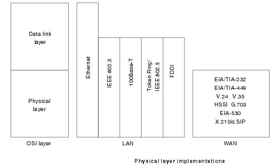
      The physical layer defines the electrical, mechanical, procedural, and functional specifications for activating, maintaining, and deactivating the physical link between communicating network systems. Physical layer specifications define characteristics such as voltage levels, the timing of voltage changes, physical data rates, maximum transmission distances, and physical connectors. Physical layer implementations can be categorized as either LAN or WAN specifications.

      Figure: Physical Layer Implementations Can Be LAN or WAN Specifications
      OSI Model Data Link Layer
      The data link layer provides reliable transit of data across a physical network link. Different data link layer specifications define different network and protocol characteristics, including physical addressing, network topology, error notification, sequencing of frames, and flow control. Physical addressing (as opposed to network addressing) defines how devices are addressed at the data link layer. Network topology consists of the data link layer specifications that often define how devices are to be physically connected, such as in a bus or a ring topology. Error notification alerts upper-layer protocols that a transmission error has occurred, and the sequencing of data frames reorders frames that are transmitted out of sequence. Finally, flow control moderates the transmission of data so that the receiving device is not overwhelmed with more traffic than it can handle at one time.
      The Institute of Electrical and Electronics Engineers (IEEE) has subdivided the data link layer into two sublayers: Logical Link Control (LLC) and Media Access Control (MAC).
      Figure: The Data Link Layer Contains Two Sublayers
      The Logical Link Control (LLC) sublayer of the data link layer manages communications between devices over a single link of a network. LLC is defined in the IEEE 802.2 specification and supports both connectionless and connection-oriented services used by higher-layer protocols. IEEE 802.2 defines some fields in data link layer frames that enable multiple higher-layer protocols to share a single physical data link. The Media Access Control (MAC) sublayer of the data link layer manages protocol access to the physical network medium. The IEEE MAC specification defines MAC addresses, which enable multiple devices to uniquely identify one another at the data link layer.

      Examples of data link protocols are Ethernet for local area networks (multi-node), the Point-to-Point Protocol (PPP), HDLC and ADCCP for point-to-point (dual-node) connections.

      OSI Model Network Layer

      The network layer defines the network address, which differs from the MAC address. Some network layer implementations, such as the Internet Protocol (IP), define network addresses in a way that route selection can be determined systematically by comparing the source network address with the destination network address and applying the subnet mask. Because this layer defines the logical network layout, routers can use this layer to determine how to forward packets. Because of this, much of the design and configuration work for internetworks happens at Layer 3, the network layer.

      OSI Model Transport Layer

      The transport layer accepts data from the session layer and segments the data for transport across the network. Generally, the transport layer is responsible for making sure that the data is delivered error-free and in the proper sequence. Flow control occurs typically at the transport layer.
      Flow control manages data transmission between devices so that the transmitting device does not send more data than the receiving device can process. Multiplexing enables data from several applications to be transmitted onto a single physical link. Virtual circuits are established, maintained, and terminated by the transport layer. Error checking involves creating various mechanisms for detecting transmission errors, while error recovery involves acting, such as requesting that data be retransmitted, to resolve any errors that occur.
      The transport protocols used on the Internet are TCP and UDP.

      OSI Model Session Layer

      The session layer establishes, manages, and terminates communication sessions. Communication sessions consist of service requests and service responses that occur between applications located in different network devices. These requests and responses are coordinated by protocols implemented at the session layer. Some examples of session-layer implementations include Zone Information Protocol (ZIP), the AppleTalk protocol that coordinates the name binding process; and Session Control Protocol (SCP), the DECnet Phase IV session layer protocol.

      OSI Model Presentation Layer

      The presentation layer provides a variety of coding and conversion functions that are applied to application layer data. These functions ensure that information sent from the application layer of one system would be readable by the application layer of another system. Some examples of presentation layer coding and conversion schemes include common data representation formats, conversion of character representation formats, common data compression schemes, and common data encryption schemes.
      Common data representation formats, or the use of a standard image, sound, and video formats, enable the interchange of application data between different types of computer systems. Conversion schemes are used to exchange information with systems by using different text and data representations, such as EBCDIC and ASCII. Standard data compression schemes enable data that is compressed at the source device to be properly decompressed at the destination. Standard data encryption schemes enable data encrypted at the source device to be properly deciphered at the destination.
      Presentation layer implementations are not typically associated with a particular protocol stack. Some well-known standards for video include QuickTime and Motion Picture Experts Group (MPEG). QuickTime is an Apple Computer specification for video and audio, and MPEG is a standard for video compression and coding.
      Among the well-known graphic image formats are Graphics Interchange Format (GIF), Joint Photographic Experts Group (JPEG), and Tagged Image File Format (TIFF). GIF is a standard for compressing and coding graphic images. JPEG is another compression and coding standard for graphic images, and TIFF is a standard coding format for graphic images.

      OSI Model Application Layer

      The application layer is the OSI layer closest to the end user, which means that both the OSI application layer and the user interact directly with the software application.
      This layer interacts with software applications that implement a communicating component. Such application programs fall outside the scope of the OSI model. Application layer functions typically include identifying communication partners, determining resource availability, and synchronizing communication.
      When identifying communication partners, the application layer determines the identity and availability of communication partners for an application with data to transmit. When determining resource availability, the application layer must decide whether sufficient network resources for the requested communication exist. In synchronizing communication, all communication between applications requires cooperation that is managed by the application layer.
      Some examples of application layer implementations include Telnet, File Transfer Protocol (FTP), and Simple Mail Transfer Protocol (SMTP).
      OSI, TCP/IP and Encapsulation
      C. Describe the purpose of the various address types at different OSI layers.

      Internetwork Addressing

      Internetwork addresses identify devices separately or as members of a group. Addressing schemes vary depending on the protocol family and the OSI layer. Three types of internetwork addresses are commonly used: data link layer addresses, Media Access Control (MAC) addresses, and network layer addresses.

      Data Link Layer Addresses

      A data link layer address uniquely identifies each physical network connection of a network device. Data-link addresses sometimes are referred to as physical or hardware addresses. Data-link addresses usually exist within a flat address space and have a pre-established and typically fixed relationship to a specific device.
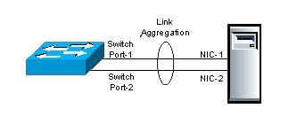
      End systems generally have only one physical network connection and thus have only one data-link address. Routers and other internetworking devices typically have multiple physical network connections and therefore have multiple data-link addresses.
      Figure: Each Interface on a Device Is Uniquely Identified by a Data-Link Address illustrates how each interface on a device is uniquely identified by a data-link address.
      Figure: Each Interface on a Device Is Uniquely Identified by a Data-Link Address
      Technology Handbook-01-2-13.jpg

      MAC Addresses

      Media Access Control (MAC) addresses consist of a subset of data link layer addresses. MAC addresses identify network entities in LANs that implement the IEEE MAC addresses of the data link layer. As with most data-link addresses, MAC addresses are unique for each LAN interface.
      Figure: MAC Addresses, Data-Link Addresses, and the IEEE Sublayers of the Data Link Layer Are All Related illustrates the relationship between MAC addresses, data-link addresses, and the IEEE sublayers of the data link layer.
      Figure: MAC Addresses, Data-Link Addresses, and the IEEE Sublayers of the Data Link Layer Are All Related
      CT840114.jpg
      MAC addresses are 48 bits in length and are expressed as 12 hexadecimal digits. The first 6 hexadecimal digits, which are administered by the IEEE, identify the manufacturer or vendor and thus comprise the Organizationally Unique Identifier (OUI). The last 6 hexadecimal digits comprise the interface serial number or another value administered by the specific vendor. MAC addresses sometimes are called burned-in addresses (BIAs) because they are burned into read-only memory (ROM) and are copied into random-access memory (RAM) when the interface card initializes.
      Figure: The MAC Address Contains a Unique Format of Hexadecimal Digits
      CT840115.jpg

      Mapping Addresses

      Because internetworks generally use network addresses to route traffic around the network, there is a need to map network addresses to MAC addresses. When the network layer has determined the destination station’s network address, it must forward the information over a physical network using a MAC address. Different protocol suites use different methods to perform this mapping, but the most popular is Address Resolution Protocol (ARP).
      Different protocol suites use different methods for determining the MAC address of a device. The following three methods are used most often. Address Resolution Protocol (ARP) maps network addresses to MAC addresses. The Hello protocol enables network devices to learn the MAC addresses of other network devices. MAC addresses either are embedded in the network layer address or are generated by an algorithm.
      Address Resolution Protocol (ARP) is the method used in the TCP/IP suite. When a network device needs to send data to another device on the same network, it knows the source and destination network addresses for the data transfer. It must somehow map the destination address to a MAC address before forwarding the data. First, the sending station will check its ARP table to see if it has already discovered this destination station’s MAC address. If it has not, it will send a broadcast on the network with the destination station’s IP address contained in the broadcast. Every station on the network receives the broadcast and compares the embedded IP address to its own. Only the station with the matching IP address replies to the sending station with a packet containing the MAC address for the station. The first station then adds this information to its ARP table for future reference and proceeds to transfer the data.
      When the destination device lies on a remote network, one beyond a router, the process is the same except that the sending station sends the ARP request for the MAC address of its default gateway. It then forwards the information to that device. The default gateway will then forward the information over whatever networks necessary to deliver the packet to the network on which the destination device resides. The router on the destination device’s network then uses ARP to obtain the MAC of the actual destination device and delivers the packet.
      The Hello protocol is a network layer protocol that enables network devices to identify one another and indicate that they are still functional. When a new end system powers up, for example, it broadcasts hello messages onto the network. Devices on the network then return hello replies, and hello messages are also sent at specific intervals to indicate that they are still functional. Network devices can learn the MAC addresses of other devices by examining Hello protocol packets.
      Three protocols use predictable MAC addresses. In these protocol suites, MAC addresses are predictable because the network layer either embeds the MAC address in the network layer address or uses an algorithm to determine the MAC address. The three protocols are Xerox Network Systems (XNS), Novell Internetwork Packet Exchange (IPX), and DECnet Phase IV.

      Network Layer Addresses

      A network layer address identifies an entity at the network layer of the OSI layers. Network addresses usually exist within a hierarchical address space and sometimes are called virtual or logical addresses.
      The relationship between a network address and a device is logical and unfixed; it typically is based either on physical network characteristics (the device is on a particular network segment) or on groupings that have no physical basis (the device is part of an AppleTalk zone). End systems require one network layer address for each network layer protocol that they support. (This assumes that the device has only one physical network connection.) Routers and other internetworking devices require one network layer address per physical network connection for each network layer protocol supported. For example, a router with three interfaces each running AppleTalk, TCP/IP, and OSI must have three network layer addresses for each interface. The router, therefore, has nine network layer addresses.
      Figure: Each Network Interface Must Be Assigned a Network Address for Each Protocol Supported illustrates how each network interface must be assigned a network address for each protocol supported.
      Figure: Each Network Interface Must Be Assigned a Network Address for Each Protocol Supported
      CT840116.jpg

      Hierarchical Versus Flat Address Space

      Internetwork address space typically takes one of two forms: hierarchical address space or flat address space. A hierarchical address space is organized into numerous subgroups, each successively narrowing an address until it points to a single device (in a manner similar to street addresses). A flat address space is organized into a single group (in a manner similar to U.S. Social Security numbers).
      Hierarchical addressing offers certain advantages over flat-addressing schemes. Address sorting and recall is simplified using comparison operations. For example, “Ireland” in a street address eliminates any other country as a possible location.
      Figure: Hierarchical and Flat Address Spaces Differ in Comparison Operations illustrates the difference between hierarchical and flat address spaces.
      Figure: Hierarchical and Flat Address Spaces Differ in Comparison Operations
      Technology Handbook-01-2-17.jpg

      Address Assignments

      Addresses are assigned to devices as one of two types: static and dynamic. Static addresses are assigned by a network administrator according to a preconceived internetwork addressing plan. A static address does not change until the network administrator manually changes it. Dynamic addresses are obtained by devices when they attach to a network, using some protocol-specific process. A device using a dynamic address often has a different address each time that it connects to the network. Some networks use a server to assign addresses. Server-assigned addresses are recycled for reuse as devices disconnect. A device is therefore likely to have a different address each time that it connects to the network.

      Addresses Versus Names

      Internetwork devices usually have both a name and an address associated with them. Internetwork names typically are location-independent and remain associated with a device wherever that device moves (for example, from one building to another). Internetwork addresses usually are location-dependent and change when a device is moved (although MAC addresses are an exception to this rule). As with network addresses being mapped to MAC addresses, names are usually mapped to network addresses through some protocol. The Internet uses Domain Name System (DNS) to map the name of a device to its IP address. For example, it’s easier for you to remember http://www.cisco.com instead of some IP address. Therefore, you type http://www.cisco.com into your browser when you want to access Cisco’s web site. Your computer performs a DNS lookup of the IP address for Cisco’s web server and then communicates with it using the network address.

      GLOSSARY 


      1. FTP (File Transfer Protocol) – Used to transfer files over the internet using TCP/IP.
      2. HTTP (Hypertext Transfer Protocol) – Underlining protocol used by the World Wide Web. Allows Web servers and browsers to communicate with each other.
      3. SMTP (Simple Mail Transfer Protocol) – Protocol used to send email messages between servers.
      4. DNS (Domain Name Service) – An internet service that translates domain names, such as http://www.yahoo.com, into IP addresses.
      5. TFTP (Trivial File Transfer Protocol) – Simplified version of the FTP protocol which has no security features.
      6. NFS (Network File System) – Client/Server application designed by SUN MICROSYSTEMS to allow all network users to access files stored on different computer types.
      7. Telnet – terminal emulation program that allows you to connect to a server and enter information and commands similar to if you were actually on the server terminal.
      8. ASCII – a code for representing English characters as numbers.
      9. EBCDIC (Extended Binary-Coded Decimal Interchange Code) – IBM code for representing characters as numbers.
      10. MIDI (Musical Instrument Device Interface) – adopted by the electronic music industry for controlling devices, such as synthesizers and sound cards, that emit music.
      11. MPEG (Moving Pictures Experts Group) – the family of digital video compression standards and file formats developed by the ISO group.
      12. JPEG (Joint Photographic Experts Group) – a lossy compression format for color images that reduces file size by 5% while losing some image detail.
      13. SQL (Structured Query Language) – a standardized query language for requesting information from a database.
      14. RPC (Remote Procedure Call) – allows a program on one computer execute a program on a server.
      15. TCP (Transmission Control Protocol) – enables two to establish a connection and exchange streams of data.
      16. UDP (User Datagram Protocol) – offering a direct way to send and receive datagrams over an IP network with very few error recovery services.
      17. IP (Internet Protocol) – specifies the format of packets and the addressing schemes.
      18. ICMP (Internet Control Message Protocol) – an extension of IP which supports packets containing error, control, and informational messages.
      19. ARP (Address Resolution Protocol) – used to convert an IP address to a physical address.
      20. PING – a utility to check if an IP address is accessible.
      21. Traceroute – utility that tracks a packet from your computer to an internet host showing how many hops and how long it took.
      22. IEEE 802.2 – divides the data link layer into two sublayers — the logical link control (LLC) layer and the media access control (MAC) layer.
      23. 802.3 – Defines the MAC layer for bus networks that use CSMA/CD. This is the basis of the Ethernet standard.
      24. 802.5 – Defines the MAC layer for token-ring networks.

      ================================================================