• VMworld General Session

    VMworld General Session

    We are the tomorrow, people not customers. It is an intriguing way to get this general session started, nice performance. Pat inform us that Digital Transformation is the top tech buzz word. What does it mean to you? The digital transformation we are having now is all about the cloud. By 2020 the ratio of workloads on the cloud to traditional IT will be 50/50, by 2030 the public cloud will pass the 50% mark. How do we prepare? We can say with some certainty that less and less business are going to be investing in their own hardware and start using  more XaaS.

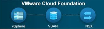
    2016-08-29 09.23.25.jpg This is why the be_tomorrow is us and is now. And to support this revolution VMware is a leader in the SDDC (software Defined Data Center) field. Pat introduces the cross-cloud architecture to provide freedom and control with the VMware Cloud Foundation.

    2016-08-29 09.34.36.jpg

    IBM is the first partner offering the Cloud Foundation as a service. They mentioned that they already have 500 customers using these services. the main idea of the cloud Foundation is to make the cloud simple.

    Screenshot 2016-08-29 09.40.14.png

    Going back to my first post yesterday morning about my Datacenter wishes, it seems that VMware is my genie. Now switching gears to the Cross-Cloud services from VMware. Is nice to see that VMware is not pretending to run any app, on any device, on their cloud, but the last part of that catch phrase really becomes any cloud.

    2016-08-29 09.45.46

    It is not possible to go back to our clients and tell them to stop using AWS or Azure, it is better to embrace their diversity and wrap the solution around those external services.

    We now have a layer that can move workloads between AWS, Azure, and Google. Micro-segmentation and network virtualization for the public cloud. This is huge! Any application, any device, and now for real any cloud!

    be_tomorrow together!

  • be_here

    be_here

    I am back at VMworld Las Vegas, and once again I am surrounded by the most creative group of people in my line of work. Last year we were ready for any, this year we’ll be_here. What is it that you want to be_? From the customer point of view, I want to have access to my applications from anywhere and all the time. From the engineering point of view, I want to design a system that can accomplish that in the most efficient and simple way possible. I am hearing wonderful things already, most involving NSX.

    One of the buzz phrases that I like the most this year is be_free, we want to be free to move our workloads with no borders, on-prem and off. We are getting there. What is your Datacenter wish list?  I know mine is to have one logical Datacenter span across multiple physical locations seamlessly.  I know that is already possible, some people are doing it. I also know that a huge number of users are not prepared for disasters, and sometimes they are not protected for even the most simple of events. I want to offer a solution that solves all the business continuity challenges in an implicit way. A turned key solution without a thousand parts glued by chewing gum, easy to scale both up and out, and one that can be upgraded with no downtime.

    All this is possible, and this week  I will be on the lookout for this new set of mind, don’t talk to me about old iron, and like an ex-coworker of mine used to say “don’t put lipstick on a pig”. I want to be_tomorrow.

  • Create WWNN and WWPN pools in UCS Manager

    This is part of a series of posts on how to initially configure you UCS B-Series system using UCS manager. With the information in this post, you will be able to configure the vHBAs needed for FC connectivity. Check the other posts under the Cisco section in my blog. If you are using iSCSI you can skip this step of the UCS B-Series configuration.

    To start login into your UCS Manager, select the SAN Tab and Navigate to the Pool section. Right click on WWNN and click Create WWNN Pool

    create-wwnn.png

    Give it a name, select Sequential and clock Next.

    Screenshot 2016-07-15 12.37.05

    Now add the value for the WWNN, first click add then fill the quantity (in this case 16) and cick Ok and Finish.

    Screenshot 2016-07-15 12.40.06The WWPN pool creation process is analog to the one just described, but chage one of the its on the WWN window (see below)

    Screenshot 2016-07-15 12.44.37

    That’s it for this post, I am trying to keep them short to keep them coming. On the next post, I will show how to create a VLAN.


  • UCS B-Series Start to Finish – Part 3

    Now that we have our system up to date with the latest software, we can start configuring the different templates, pools, and policies. The UCS is a stateless system, meaning that you will be able to abstract all the usual properties (UUID, MAC Address, etc…) into a Service Profile and apply those to any compatible hardware.

    • Create a Sub-Organization:  this step is recommended for multitenant implementations, it doesn’t hurt to make it the standard installation procedure. Right-Click on Sub-Organization to open the Create Organization window.

    Screenshot 2016-05-06 12.54.42

    • Create the UUID Pool: select the Server Tab, select Pools from the drop down menu, expand the Sub-Organizations and expand the new Sub-Organization (in this case Sub-Org-01). Select the UUID Suffix Pools and click Add.

    Screenshot 2016-05-06 13.16.50.png

    • Type in a name and select Sequential, then click Next

    Screenshot 2016-05-06 13.22.01

    • Click Add to define the value

    Screenshot 2016-05-06 13.22.21

    • Change one digit to make it unique and add in a decent size to configure it once and forget about it. the click Finish and click OK in the resulting pop-up window.

    Screenshot 2016-05-06 13.22.51

    • Create an IP address pool: this pool will be used to connect to the KVM for console access. First, navigate to the LAN tab and select Pools from the drop down menu, then under the Sub-Organization (Sub-Org-01 in this case) right click and select Create IP Pool.

    Screenshot 2016-05-11 11.16.09

    • Give at name, select Sequential and click Next

    Screenshot 2016-05-11 11.16.36

    • Click Add to define the IP address block.

    Screenshot 2016-05-11 11.16.56

    • Setup the IP address block information, you can do as many as you want, you can always add later, I usually configure one for each blade at the very beginning ad forget about it.

    Screenshot 2016-05-11 11.17.32

    • As a final step, click Next and then click Finish (assuming you won’t use IPv6).

    Screenshot 2016-05-11 11.17.53.png

    • Create a Server Pool: from the Servers tab, navigate to the Sub-Organization and with a right-click select Create Server Pool. Once there type in a name for the pool and click Next.

    create-pool.png

    • Select the blades and servers from the left pane and add them to the Pooled Servers pane, and click Finish.

    Screenshot 2016-05-11 08.13.12

    • Create the MAC Address Pools: We could use the default pool, or we can get very creative with this, especially if you are using VMware or any other host with multiple vNICs. The trick here is to Identify the FI, chassis, site, etc.
    The MAC address is going to be of the format 00:25:B5:00:00:00, the first part
    (00:25:B5) is the Organizationally Unique Identifier (OUI) and the second part
    (00:00:00) id the Device ID, and the second part is the one that we customize.

    Is with the second part that we will get creative. Use it to identify the site and FI, and I go even further and if the deployment is small I also identify the vSwitch. For example 00:25:B5:1A:00:00 could be Site 1, FI A, vSwitch 0, and the last three places are for sequential values. Check the following image with a few MAC Pools.


    Screenshot 2016-05-11 16.44.45.png

    In the previous image, you can see separate sets for management, vMotion, iSCSI, and VM traffic. You don’t have to do it exactly as I have it there, maybe you want to use the same vSwitch for management and vMotion, then you could designate one place as the vmk# for example. The next slideshow has the MAC Pool creation process.


    I am going to submit this post the way I have it up to this point and then release the next steps including:

    Create WWNN and WWPN pools (if you are using FC).

    Create VLANs.

    Create Policies.

    Create vNIC and vHBA templates.

    Create a Service Profile Template.

    Deploy Service Profiles from the Service Profile Template.

    Configure Especial Cases like Layer-2 Disjoint Networks

  • How to Use GitHub and Atom

    I’ve decided to learn a little bit more about how to use GitHub because I want to start writing some automation code for the UCS B-Series configuration. I did some research on which editor to use (I’ve only used vi, that was the last time I coded) and I found that Atom (www.atom.io) is really sleek and that it integrates with programming languages and you can git directly from it. I will try to present my findings in the next few paragraphs.

    In Summary:

    • Go to http://www.github.com and create an account by clicking the ‘Sign up‘ button on the top right.

    This slideshow requires JavaScript.

    • Create a Repository (project): You can Read the guide or Start a project directly:

    screenshot-2017-02-08-14-48-06

    • Copy the Clone/Download URL

    screenshot-2017-02-08-14-51-22

    • git clone the URL (If you don’t have git installed, check this post from Chris Chernoff explaining how to go about it).
    Mac:~ prmadness$ pwd
    /Users/prmadness
    Mac:~ prmadness$ which git
    /usr/bin/git
    Mac:~ prmadness$ git clone https://github.com/prmadness/new_project.git
    Cloning into 'new_project'...
    remote: Counting objects: 3, done.
    remote: Total 3 (delta 0), reused 3 (delta 0), pack-reused 0
    Unpacking objects: 100% (3/3), done.
    Mac:~ prmadness$  ls -ld new_project
    drwxr-xr-x  4 prmadness  staff  136 Feb  8 15:06 new_project/
    Mac:~ prmadness$ cd new_project/
    Mac:new_project prmadness$ pwd
    /Users/prmadness/new_project

    With the previous section, I demonstrated how to download or clone the project or repository into your computer. Now let’s move on to the Atom editor:

    • Download the Atom editor from www.Atom.io, then install and start the application.
    • Open the Atom editor and under the File menu click on “Add Project Folder”, Then select the project folder that came down from the git clone.

    screenshot-2017-02-08-15-29-09

    • In the Atom editor, write your python code and save the file to the repository folder using a .py extension. In this example, we will use the filename “ucs-config.py
    • If the atom-runner package is installed, you could execute the code directly from Atom pressing CTRL-R on your keyboard.
    • Go back to the command line (Terminal) and execute the following commands:
    Mac:$cd new_project/
    Mac:ucs-config prmadness$ pwd
    /Users/prmadness/new_project
    Mac:ucs-config prmadness$ git status
    On branch master
    Your branch is up-to-date with 'origin/master'.
    Untracked files:
      (use "git add ..." to include in what will be committed)
    
        ucs-config.py
    
    nothing added to commit but untracked files present (use "git add" to track)
    • Execute “git add ucs-config.py” and “git status” again
    git add ucs-config.py 
    Mac:ucs-config prmadness$ git status
    On branch master
    Your branch is up-to-date with 'origin/master'.
    Changes to be committed:
      (use "git reset HEAD ..." to unstage)
    
        new file:   ucs-config.py
    • Execute “git commit -m “message”
    Mac:ucs-config prmadness$ git commit -m "first commited file"
    [master c04a7ac] first commited file
     1 file changed, 6 insertions(+)
     create mode 100644 ucs-config.py
    • At this point, the new file is committed to the project in my laptop, but not synced up.
    • Execute “git push
    Mac:ucs-config prmadness$ git push
    warning: push.default is unset; its implicit value has changed in
    Git 2.0 from 'matching' to 'simple'. To squelch this message
    and maintain the traditional behavior, use:
    
      git config --global push.default matching
    
    To squelch this message and adopt the new behavior now, use:
    
      git config --global push.default simple
    
    When push.default is set to 'matching', git will push local branches
    to the remote branches that already exist with the same name.
    
    Since Git 2.0, Git defaults to the more conservative 'simple'
    behavior, which only pushes the current branch to the corresponding
    remote branch that 'git pull' uses to update the current branch.
    
    See 'git help config' and search for 'push.default' for further information.
    (the 'simple' mode was introduced in Git 1.7.11. Use the similar mode
    'current' instead of 'simple' if you sometimes use older versions of Git)
    
    Username for 'https://github.com': prmadness
    Password for 'https://prmadness@github.com': 
    Counting objects: 3, done.
    Delta compression using up to 8 threads.
    Compressing objects: 100% (3/3), done.
    Writing objects: 100% (3/3), 346 bytes | 0 bytes/s, done.
    Total 3 (delta 0), reused 0 (delta 0)
    To https://github.com/prmadness/ucs-config.git
       fab300a..c04a7ac  master -> master
    • If this was your first time pushing a file, execute “git config –global push.default simple” to get rid of the legacy message.
    • Everyone else who wants to have the latest revision of your project must execute a “git pull” if they already cloned the project or the “git clone URL” command to download the whole project.
    • All these git commands work when you are in the repository path/folder of your laptop, use the “pwd” command to check your current path.
    • Execute git with no arguments to display the Help:
    Mac:ucs-config prmadness$ git
    usage: git [--version] [--help] [-C <path>] [-c name=value]
               [--exec-path[=<path>]] [--html-path] [--man-path] [--info-path]
               [-p | --paginate | --no-pager] [--no-replace-objects] [--bare]
               [--git-dir=<path>] [--work-tree=<path>] [--namespace=<name>]
               <command> [<args>]
    
    These are common Git commands used in various situations:
    
    start a working area (see also: git help tutorial)
       clone      Clone a repository into a new directory
       init       Create an empty Git repository or reinitialize an existing one
    
    work on the current change (see also: git help everyday)
       add        Add file contents to the index
       mv         Move or rename a file, a directory, or a symlink
       reset      Reset current HEAD to the specified state
       rm         Remove files from the working tree and from the index
    
    examine the history and state (see also: git help revisions)
       bisect     Use binary search to find the commit that introduced a bug
       grep       Print lines matching a pattern
       log        Show commit logs
       show       Show various types of objects
       status     Show the working tree status
    
    grow, mark and tweak your common history
       branch     List, create, or delete branches
       checkout   Switch branches or restore working tree files
       commit     Record changes to the repository
       diff       Show changes between commits, commit and working tree, etc
       merge      Join two or more development histories together
       rebase     Reapply commits on top of another base tip
       tag        Create, list, delete or verify a tag object signed with GPG
    
    collaborate (see also: git help workflows)
       fetch      Download objects and refs from another repository
       pull       Fetch from and integrate with another repository or a local branch
       push       Update remote refs along with associated objects
    
    'git help -a' and 'git help -g' list available subcommands and some
    concept guides. See 'git help <command>' or 'git help <concept>'
    to read about a specific subcommand or concept.

    The preceding steps came from these two videos:

    Two things I learned after watching those videos:

    1. Add the terminal-plus package to Atom to open a terminal on you current repository and execute the git commands directly from the Atom editor.
    2. As an alternative to the command line add the git-plus package to use git directly from the Atom editor, after it is installed press “Command+Shift+P” to add, commit and push. To learn how to use git from atom check this video:

    As always, excuse my grammar and lack of details, I mostly write these blogs to be able to remember the things I use once a month.

  • Data Migration Using Nimble Replication

    As part of the service portfolio at ABS Technology, we offer Data Center migrations. There are multiple technologies to achieve the data replication necessary in a migration. There are two main levels, host-level replication, and array level replication. With host replication, the granularity is a single operating system instance, it can be physical or virtual. You can use technologies like the vSphere Replication Appliance, Recoverpoint for VM’s, VEEAM, ZERTO, or Double-Take. All of these differ and the use of one vs the other will depend on a number of factors like RPO/RTO, budget, standardization policy, etc.

    When it comes to array replication, you will have as many flavors as array vendors, but the two types are Asynchronous and Synchronous, again the selection of technology will depend on the requirements.

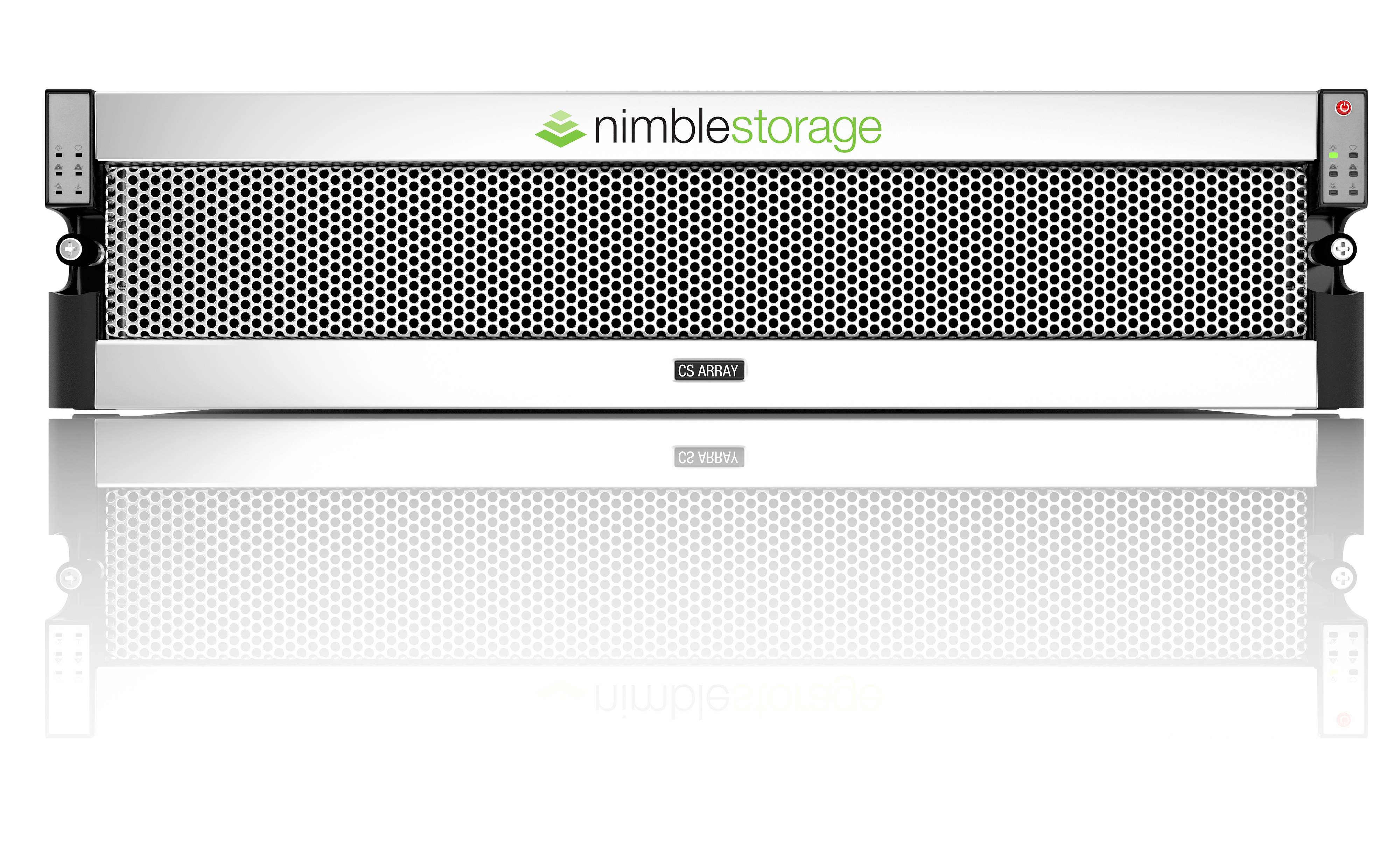
    In this post, I will summarize what is needed for a migration from one Data Center to another of an environment using a UCS B-Series, a Nimble Storage Array, and vSphere.

    In the Nimble storage array, the replication can be done over the Data subnet or the management subnet. If the array has a free NIC, you can configure it for data, but use it only for replication. this last case is the one I will be documenting here.

    The first step is to configure the subnet in the Nimble Storage. I will user the network 10.10.10.0/24 as an example, with a discovery IP of 10.10.10.50 and an IP address of 10.10.10.51. The discovery IP will not be used because we will only use this subnet for replication purposes.

    Figure 1. From the Administration main menu, select Network Configuration.

    Screenshot 2016-05-09 10.44.52

    Figure 2. Click on Active Settings

    Screenshot 2016-05-09 10.48.38.png

    Figure 3. Click the Subnets tab and then click the Edit button.

    Screenshot 2016-05-09 10.58.38

    Figure 4. Then click the Add  button

    Screenshot 2016-05-09 11.02.09.png

    Figure 5. Click Done to finish.

    Screenshot 2016-05-09 09.24.58

    As a final step, you can save the new configuration in the active settings by clicking the Update button, or save it as a draft to be applied later by selecting the Save as Draft button.

    The next step is to configure the replication partner. You will need the nimble Group Name of each storage array, the hostname or IP address and a password to use as a shared secret.

    In the next four images, we will navigate through the process of setting the replication partner. First, log in the Nimble and from the menu select Manage->Protection->Replication Partners.

    Figure 6. From the menu select Manage->Protection->Replication Partners.

    AA-Manage-Protection-Replication_Partners

    Figure 7. Click on the New Replication Partner button.

    B-Click-New-replication-Partner

    Figure 8. Input the information, in our case select the newly created network from the drop down menu as a Replication Network (see Figure 5 above).

    CC-Rep-Partner_Info

    Figure 9. Create an optional QoS policy and click Finish.

    D-QoS

    In the following slideshow, I configure the Volume Collection. The Volume Collection contains all the volumes that will replicate at the same time. At the end, you can see the way I would monitor the replication.

    This slideshow requires JavaScript.

    Now that everything is replicating, wait for it to be synchronized and it’s time to migrate. There can be multiple ways to do this, you could clone a replica and chose the VM’s you want to migrate, or you could “Handover” the complete volume collection.

    Option one: Create clone of the replica.

    In this case, the pre-requisite is to stop I/O on the source VM, Datastore, or Volume collection. Do this to have a crash consistent copy of the source. After you stop the I/O, wait for the last replica to happen and now in the destination array, clone the volume replica snapshot and put it online. Then configure the cloned Volume for Host access. If you are satisfied with your VM, I would suggest a storage vMotion of that VM to another DS not involved in the replication and remove the clone. Just to keep things clean.

    Option two: Handover the Volume Collection.

    Screenshot 2016-05-24 13.33.53

    Before you click on that Handover button, make sure you shutdown your VMs and unmount the Datastores (don’t delete them!). In the case of a migration to a new set of hosts without replication back, remove the old hosts access to the volumes and rescan to remove dead paths.

     

  • Netbackup Appliance Protection Override

    Back in 1999, we hired a guy from Veritas to install our first Netbackup software, version 3.5 it was (I think). Little I knew that it would be 2016 and I would still be working with this. It outlived other things that look more promising at that time.

    I wanted to create this quick post about how to gain root access to a Netbackup appliance because it changed a little bit from version 2.6 to version 2.7. See my input in red.

    login as: admin
    admin@<ip>'s password: <password>
    Last login: Wed May  4 09:52:28 2016 from <my mac>
    
    Appliance  Manage master and media appliances.
    Exit       Log out and exit from the current shell.
    Manage     Manage NetBackup appliance.
    Monitor    Monitor NetBackup appliance activities.
    Network    Network Administration.
    Reports    Examine the running and historical state of the host.
    Settings   Change NetBackup appliance settings.
    Shell      Shell operations.
    Support    NetBackup Support.
    
    <NBU-Appliance-Hostname>.Main_Menu> Support
    Entering NetBackup support view...
    
    Checkpoint      Appliance Checkpoint Management.
    DataCollect     Gather device logs.
    Disk            Gather disk information.
    Errors          Display NetBackup errors.
    Exit            Log out and exit from the current shell.
    FactoryReset    Reset this system to factory install image
    InfraServices   Show/control infrastructure services.
    iostat          Execute the iostat command.
    IPMI            Remote management port configuration.
    KillRemoteCall  Terminate running or hung remote calls on peer compute nodes.
    Logs            Set level, share, unshare, view, and upload debug logs.
    Maintenance     Launch maintenance shell.
    Messages        Display the messages file.
    NBDNA           Network traces with NBDNA tool (Select Create or Remove).
    Nbperfchk       Execute the disk IO or network bandwidth check.
    NBSU            Manage NetBackup support data files (Select Create or Remove).
    Processes       Show/control NetBackup and Admin Console processes.
    Reboot          Reboot the system.
    RecoverStorage  View or delete directories backed up during appliance re-image.
    Return          Return to the previous menu.
    Service         Service management.
    Shell           Shell operations.
    Show            Display information.
    Shutdown        Power off the system.
    Storage         Storage data and configuration
    Test            Test the current status of various appliance components.
    
    <NBU-Appliance-Hostname>.Support> Maintenance
    <!-- Maintenance Mode --!>
    maintenance's password: <password>
    (this script was for 2.6)
    maintenance-!> /opt/Symantec/scspagent/IPS/sisipsoverride.sh
    bash: /opt/Symantec/scspagent/IPS/sisipsoverride.sh: No such file or directory
    (this is the right script for 2.7)
    maintenance-!> /opt/Symantec/sdcssagent/IPS/sisipsoverride.sh
    Symantec Data Center Security Server Policy Override
    
        Agent Version: 6.5.0 (build 355)
       Current Policy: NetBackup Appliance Prevention Policy, r38
    Policy Prevention: Enabled
      Policy Override: Allowed
       Override State: Not overridden
    
    To override the policy and disable protection, enter your login password.
    Password: <password>
    
    Choose the type of override that you wish to perform:
     1. Override Prevention except for Self-Protection
     2. Override Prevention Completely
    Choice? [1] 2
    
    Choose the amount of time after which to automatically re-enable:
     1. 15 minutes
     2. 30 minutes
     3. 1 hour
     4. 2 hours
     5. 4 hours
     6. 8 hours
    Choice? [1] 4
    
    Enter a comment. Press Enter to continue.
    <comment or just Press Enter>
    Please wait while the policy is being overridden.
    .................
    
    The policy was successfully overridden.
    maintenance-!> elevate
    <NBU-Appliance-Hostname>:/home/maintenance #
  • UCS B-Series Start to Finish: Part 2

    After the initial setup is done, I recommend to go ahead and install the latest available firmware  to get the most out of your environment. First, go to http://www.cisco.com, and from the Support Menu, click “All downloads.”

    Image 1. Cisco Support Site – > All Downloads

    Screenshot 2016-05-05 14.30.02

    Note: just hover over Support, don’t click

    Image 2. Select The UCS B-Series Blade Server Software

    Screenshot 2016-05-05 14.31.58

    Image 3. Select the Server Software Bundle

    Screenshot 2016-05-05 14.33.05

    Image 4. Select the UCS Manager version and download the respective bundles.

    Screenshot 2016-05-05 14.37.42

    Number one (1) is the UCS Manager release version, number two (2) is the Blade Firmware, number three (3) is the bundle for the C-series. The C-Series bundle is not necessary, but it’s recommended to upload it too. Number four (4) is the UCS Manager and the FI firmware. With this, now your are ready to start the software update.

    Phase 1: Pre-Work

    • Check that the NTP is configured and working (view Figure 6 on Part 1)
    • Take note of the management interfaces IP addresses and check that the admin status is enabled.

    Screenshot 2016-05-05 14.56.21

    • Backup the UCS configuration

    Screenshot 2016-05-05 15.02.40

    • Verify the status of each FI, the status should be ok and green before proceeding.

    Screenshot 2016-05-05 15.07.47

    • Verify that the IO modules are up and operable

    Screenshot 2016-05-05 15.12.06

    • If the environment has been previously configured and is in production, check that all the servers (and all the rest of the equipment in general) are working correctly.

    Screenshot 2016-05-05 15.14.29

    • Verify that there is available capacity for the upgrade. If space is low delete any packages that are not in use (from the same place we will upload the packages later).

    Screenshot 2016-05-05 15.22.27

    • Before upgrading to Cisco UCS Manager Release 3.1, ensure that the key ring in use has a modulus size of 2048 bits or more by doing the following:
      • Connect to the UCS manager via ssh
      • Verify the modulus size of the key ring in use by using the following commands:
    UCS-A# scope security
    UCS-A /security # scope keyring keyring-name 
    UCS-A /security/keyring # show detail
    • If the default key ring is in use and has a modulus size less than 2048 bits, reconfigure the modulus size to 2048 bit or more, and regenerate the certificate by using the following commands:
    UCS-A# scope security
    UCS-A /security # scope keyring default
    UCS-A /security/keyring # set modulus mod2048
    UCS-A /security/keyring # set regenerate yes
    UCS-A /security/keyring # commit-buffer
    UCS-A /security/keyring # show detail
    • Upload the packages, click on the plus sign to upload the files.

    Screenshot 2016-05-05 15.26.44.png

    Check the Cisco UCS Manager Firmware Management Guide, Release 3.1

    • If the UCS Manager cluster uses the Fiber Interconnect 6296, please verify the Hardware version. SSH into the cluster and issue the “connect nxos” command, then “show module”

    Screenshot 2017-07-06 11.41.23

    • If the system has version 1.0 installed, then open a support case with Cisco to update it to version 1.1.

    Phase 2: UCS Manager

    First, we update the UCS Manager software.

    • Equipment->Equipment->Firmware Management->Installed Firmware->Activate Firmware

    Screenshot 2016-05-05 15.52.25

    • Click on the drop-down menu to select the new version

    Screenshot 2016-05-05 15.52.15

    • In case this error message pops:

    Screenshot 2017-07-06 11.50.56.png

    • Go ahead and clear the start up version and try again:

    cli-startup-version

    • Re-login after a few minutes

    relogin

    Phase 3: FI Firmware

    • Equipment->Equipment->Firmware Management->Firmware Auto Install and then Click Install Infrastructure Firmware

    Screenshot 2016-05-05 16.04.55

    • Select Ignore All and click Next.

    Screenshot 2016-05-05 16.34.25.png

    • Select the version from the drop-down menu, check the Upgrade Now button and Click Finish.

    Screenshot 2016-05-05 16.35.46.png

    • Click OK

    Screenshot 2016-05-05 16.41.49.png

    • Verify the pending activities on top of the UCS manager to acknowledge the reboot of the FI’s. Verify that the hosts are working properly before the acknowledge.
    • Click Yes
    • Click OK
    • Monitor the Progress, this could take 40 minutes per FI

    Screenshot 2016-05-05 16.42.08.png

    • When the primary FI reboots, the UCS manager will disconnect, and you will have to re-login. Check the progress and reboot the secondary FI when the option appears in pending activities on top.

    Phase 4: Blade Servers

    Now is the blade server turn. If the system is in production, check that all Service Profiles have the Maintenance Policy set to User Ack to avoid an immediate reboot of the servers. Before continuing, it is advisable to check that all components are up and operable.

    • Click on the Install Server Firmware link

    Screenshot 2016-05-05 16.53.33.png

    • Follow the wizard clicking next, at the end click Install and click Confirm Install to the pop-up windows.

    Screenshot 2016-05-05 16.55.32.png

    Screenshot 2016-05-05 16.57.23.png

    Screenshot 2016-05-05 16.57.54.png

    • Monitor the progress and check the Pending Activities on the top for the Acknowledge, if the system is in production make sure you schedule a maintenance window for this.

    Screenshot 2016-05-05 16.59.21.png

    An alternative would be to create a new Firmware Policy with the new version and then apply the policy to the Service Profile or the Service Profile Template.

    With the system at the latest software version, we are ready to continue with the configuration of the Pools, Policies, and Templates.

    Part III: Pools and Policies

    Part IV: Service Profile Templates

    Part V: Storage


  • UCS B-Series Start to Finish – Part 1

    I always wanted to write about the UCS B-Series installation process, but I was always in a hurry and could not take snapshots of a real installation. Here is a summary of that I did on my last installation:

    Part I: Initial Setup

    First, you need to rack and cable the equipment. For the correct way to install the equipment in the rack please check the Cisco UCS 5108 Server Chassis Installation Guide. In this guide, you can use pages 41-49 for the Chassis rack instructions and page 81 for the power cables needed. Then check the Cisco UCS 6200 Series Fabric Interconnect Hardware Installation Guide on pages 26 to 28. The next step would be to connect to the console port in the Fiber Interconnect (FI).

    FI-Cross-Connect-Ports

    From the Guide (pp. 55-56):

    1. Plug the RJ-45 end of the serial management cable into the Console port on the fabric interconnect, and connect the DB-9 male end into the serial port on a laptop or other computer. If the computer you will use does not have a serial port, you will need to use the Serial to USB adapter. Be sure to install the drivers for your adapter.
    2. Start your terminal software.
    3. Configure the terminal software as follows:
      • The COM port for the connection you are about to establish is the connection to the fabric interconnect. You may need to look in the computer’s device manager to confirm this. Example COM1 or COM5.
      • The other connection parameters are 9600 baud, 8 data bits, no parity, 1 stop bit.
    4. Use the terminal software’s command to open the connection to the Fabric Interconnects. A session window will start, let’s take a look at the next to screenshots:

    Figure 2. Fiber Interconnect Cluster Initial Configuration (FI-A)

    UCS-FI-Setup-1

    Figure 3. Fiber Interconnect Cluster Initial Configuration (FI-B)

    UCS-FI-Setup-2

    Now you are ready to connect to your UCS manager using your browser (Using the Cluster IPv4 address from the first screenshot).

    Configure the Fiber Interconnect ports used to connect the Chassis as Server Ports. This will acknowledge the chassis and let you configure the rest.

    Figure 4. Set the Chassis ports to Server Ports

    Screenshot 2016-05-05 17.03.35

    I would like to show a few basic initial steps before we are ready to upgrade the firmware. After login into the UCS manager using your browser, change the Power Policy to “grid”. Equipment->Policies->Global Policies->Grid

    Figure 4. Power PolicyScreenshot 2016-05-05 14.03.18

    The grid redundant configuration is sometimes used when you have two power sources to power a chassis or you require greater than N+1 redundancy. If one source fails (which causes a loss of power to one or two power supplies), the surviving power supplies on the other power circuit continue to provide power to the chassis. A common reason for using grid redundancy is if the rack power distribution is such that power is provided by two PDUs and you want the grid redundancy protection in the case of a PDU failure.

    Another set of basic configuration parameters: the Call Home, the NTP and the Timezone.

    Figure 5. Call Home Setting (leave it off until everything has been configured)

    Screenshot 2016-05-05 14.02.14

    Figure 6. NTP and Timezone Settings

    Screenshot 2016-05-05 14.08.15

    In the next new blogs, I will discuss the rest of the steps for configuration.

    Part II: Firmware Upgrade

    Part III: Pools and Policies

    Part IV: Service Profile Templates

    Part V: Storage

  • Cloudcredibility

    Recently I joined this community: https://www.cloudcredibility.com, and I feel that is not fair. I mean for people like me that love leveling in a game or score points or climb the positions in a list is really difficult. I consider myself to have some kind of obsessive compulsive disorder and joining is going to give me a few long nights for a few days, until I lose interest and find the next shining thing.

    Check my stats at:
    https://www.cloudcredibility.com/profile/widget/18380